
Aluminum Housing Machining: Design and Process Decisions
Home
/
Blog
/
Aluminum Housing Machining: Design and Process Decisions
Aluminum Housing Machining: Design and Process Decisions
October 14, 2026
Table of Contents
Aluminum housing machining is a practical engineering decision for buyers responsible for aluminum housings. This guide focuses on pocket walls, main bore, cover joint, connecting these details to the drawing, manufacturing route and first-article review.
Aluminum housing machining: start with the assembled function
A useful aluminum housing machining plan begins with what the component must do after installation. For aluminum housings, write down the mating interfaces, the direction of the working load and the surfaces that establish position. A drawing that treats every face as equally important often makes inspection more expensive without clarifying whether the part will work. Separate the functional envelope from incidental shape before asking a supplier to recommend a route.
Thin walls can spring after the clamps are released, leaving the bore acceptable in the fixture but distorted at assembly.
For aluminum housing machining, the first design review should therefore connect each critical requirement to a visible feature. Ask what would happen if that feature were at either limit of its tolerance. If the answer depends on the mating part, include that information in the review rather than leaving the supplier to infer it from a single component model.
Aluminum housing machining: turn the design intent into clear drawing requirements
Put mounting datums on stable sections. Give internal corners a realistic tool radius and keep sealing lands separate from cosmetic surfaces. A uniform wall distribution is generally easier to machine than isolated thin walls beside massive bosses.
The drawing and model for aluminum housing machining need a clear order of precedence. Identify the revision, units and general tolerances, then call out exceptions at the feature itself. Do not rely on a shaded CAD image to communicate a surface requirement, an assembled condition or a material treatment. Those details can change the route even when the visible shape remains identical.
When reviewing aluminum housings, distinguish a maximum permissible envelope from a target manufacturing value. The supplier should understand which changes need engineering approval. A proposed radius, relief or access hole may make production easier, but its effect on strength, sealing, motion or interchangeability still belongs in the design decision.
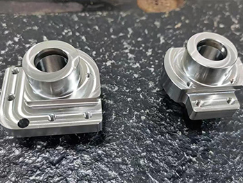
Aluminum housing machining: choose references that survive the manufacturing route
Reference and access review
A reference scheme for aluminum housing machining should be usable during production and meaningful during final inspection. Start from the surfaces that locate aluminum housings in the assembly. Review whether those surfaces exist at the first operation and whether later work will change them. Where temporary references are needed, explain how the route transfers to the finished functional references.
Clamping and locating serve different purposes in aluminum housing machining. Locators establish position; clamps keep the part supported against the process forces. An arrangement that pulls a flexible part into shape may produce a convincing result in the fixture and a different result after release. State the condition in which acceptance measurements are required.
Ask for a setup sketch when the relationship is difficult to understand. It should show contact locations, the direction of restraint and access to the critical features. The sketch does not need to reveal proprietary programming details to be useful. Its purpose is to resolve the physical assumptions that affect the finished interface.
Aluminum housing machining: match geometry to process access
Rough the pockets while enough material remains to support the walls. Review balanced stock removal, intermediate release and the final clamping arrangement before committing to a finishing route.
For aluminum housing machining, consider the complete tool and fixture envelope rather than the cutting tip alone. A feature may be reachable in CAD but blocked by a clamp, neighboring wall or machine component. Review access to the deepest or most restricted area before relaxing a useful tolerance elsewhere. Moving one nonfunctional feature can be more effective than selecting a more elaborate machine.
An economical route for aluminum housings should also leave access for cleaning and inspection. Features that become inaccessible after assembly need a defined verification point earlier in the route. This avoids discovering at final inspection that an important internal requirement cannot be checked without disassembly or sectioning.
Aluminum housing machining: separate geometry, finish and material condition
Treat material condition, dimensional geometry and surface condition as separate decisions in aluminum housing machining. A smooth surface can still be out of position. A correctly located feature can still have a damaged edge. A certificate for incoming material does not automatically describe the condition after thermal processing, joining or finishing.
For aluminum housings, mark the surfaces that need special protection and the edges that affect assembly. Where a coating or treatment changes size, define whether the drawing limit applies before or after that operation. Include any masking requirement explicitly. This gives the supplier a way to plan allowance without guessing which dimensions should be adjusted.
A aluminum housing machining review should avoid copying an exceptional capability figure onto every feature. Achievable results depend on size, geometry, restraint, material and the full route. Ask the supplier to evaluate the actual requirement and identify any limitation before price or delivery becomes the only subject of discussion.
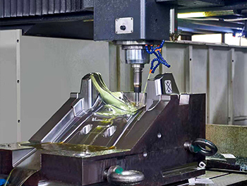
Aluminum housing machining: compare design options before the first build
The practical choice in aluminum housing machining is often between retaining a difficult feature, changing a nonfunctional detail or accepting an additional operation. Compare those options using the same assembly requirement. A cheaper process is not an improvement if it transfers adjustment work or uncertainty to the customer.
Use the comparison below to decide what belongs in the first review of aluminum housings. Request a written explanation for a proposed change, including the affected feature and the condition it is intended to improve. Keep the approved drawing as the common reference once a decision is made.
| Feature or decision | Design consideration | Inspection focus | RFQ information |
|---|---|---|---|
| Pocket walls | Leave support for finishing and avoid isolated thin sections | Check thickness and free-state shape | Identify minimum walls and approved radii |
| Main bore | Relate the bore to the mounting interface | Check size and position after release | Request bore results with datum definition |
| Cover joint | Separate sealing land from cosmetic faces | Check land flatness and local damage | State cover and gasket interface requirements |
Aluminum housing machining: use a first article to test the uncertain assumption
Illustrative troubleshooting situation
A housing that passes a bore gauge may still rock on a mounting plate. Check face flatness and bore position from the same functional datums before changing the bore tolerance.
For aluminum housing machining, use the first article to answer a specific question: does the selected geometry, reference scheme and route produce the required interface? Choose measurements or a fit trial that address that question. A sample made under exceptional conditions is useful for development, but it should not be treated as proof that the production route is stable.
Record what the first build taught you about aluminum housings, including any drawing change or process dependency. If the supplier changes the setup, material condition or finish after the trial, decide which evidence needs to be repeated. Keep successful trial measurements linked to the exact revision that produced them.
Aluminum housing machining: release a complete manufacturing package
Measure the mounting face and bore in the agreed free or restrained condition. Inspect pocket floors, threaded holes and the mating cover together where their positions interact.
Before releasing aluminum housing machining, check that the package contains the model, drawing, material condition, quantity, critical characteristics and expected inspection evidence. Include known mating constraints and any customer approval points. This is more useful than an open-ended instruction to make the part as accurately as possible.
The final aluminum housing machining decision should leave both parties able to explain what constitutes an acceptable component. Review unresolved assumptions before ordering the full quantity. If a requirement remains uncertain, identify the trial or engineering decision that will close it instead of hiding the uncertainty in a general note.
Prepare your project for a technical review
Apex lists CNC machining services among its manufacturing services. Send the drawing and requirements for your aluminum housings to discuss the actual scope. Use the material overview as a starting point, then confirm the grade, condition and project-specific feasibility in the quotation.
For further process background, see Sandvik Coromant milling application guidance. Apply tooling or joining guidance to the actual material and setup with the responsible manufacturing team. These references do not replace the approved component drawing or an application-specific qualification.
For a focused aluminum housing machining discussion, send the current model and drawing, quantity, material condition, critical interfaces and required delivery window through the form below. Identify the main uncertainty described in this guide so the engineering review can address it directly. Contact Apex Precision to request a project review and quotation.
Frequently asked questions
What is the main risk in aluminum housing machining?
Thin walls can spring after the clamps are released, leaving the bore acceptable in the fixture but distorted at assembly. Review this risk against the actual geometry and mating interfaces before selecting tolerances.
What drawing information is needed for aluminum housing machining?
Put mounting datums on stable sections. Give internal corners a realistic tool radius and keep sealing lands separate from cosmetic surfaces. A uniform wall distribution is generally easier to machine than isolated thin walls beside massive bosses.
Can aluminum housing machining use a standard process route?
Rough the pockets while enough material remains to support the walls. Review balanced stock removal, intermediate release and the final clamping arrangement before committing to a finishing route. The final route needs review against the actual drawing and quantity.
Which checks should be planned before production?
Measure the mounting face and bore in the agreed free or restrained condition. Inspect pocket floors, threaded holes and the mating cover together where their positions interact.
When should a design change be approved?
Approve a change before the supplier incorporates it into the first article or production lot. Record its effect on the mating interface, material condition and acceptance requirements, then update the controlled revision.
Latest News
Contact Us
FAQ
What types of parts can be machined?
We can machine a wide range of high-precision CNC parts for automotive, aerospace, medical devices, industrial machinery, and automation equipment, including complex geometries and custom non-standard parts.
What is the machining accuracy?
We can achieve high-precision machining with ±0.005mm tolerance and ensure consistent quality through our strict quality control system.
Can you provide small-batch and prototype manufacturing services?
Yes, we support small-batch production and prototype machining, with flexible scheduling to meet urgent client requirements.
Do you offer customized processing solutions?
Yes, we provide customized solutions with one-on-one technical support, from design review and process optimization to final machining.
How long does delivery usually take?
Delivery time depends on part complexity and quantity, typically within 1-6 weeks. We provide a detailed schedule upon order confirmation.
What certifications are available for quality management systems?
We hold ISO 9001, ISO 14001, and ISO 45001 certifications, strictly following international quality, environmental, and safety standards.
How long does delivery usually take?
Delivery time depends on part complexity and quantity, typically within 1-6 weeks. We provide a detailed schedule upon order confirmation.