CNC Machining Prototype: From CAD Validation to Functional Testing
Home
/
Blog
/
CNC Machining Prototype: From CAD Validation to Functional Testing
CNC Machining Prototype: From CAD Validation to Functional Testing
September 4, 2026
Table of Contents
Introduction
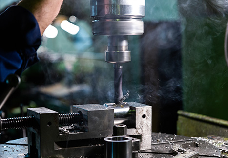
A CNC machining prototype is more than an early version of a finished component. It is an engineering tool used to verify whether a design can be manufactured accurately, assembled correctly, and perform as intended before the design moves into a more stable production stage. For mechanical components, this makes prototype machining especially valuable when dimensions, material behavior, mating features, surface conditions, and functional geometry need to be evaluated using a real engineering material.
A prototype is generally created to test a concept, design, or process before the final version is established. CNC machining extends this idea by producing prototype parts directly from metal or engineering plastic stock using controlled machining operations. Unlike purely visual models, a CNC machining prototype can often be evaluated under realistic assembly and mechanical conditions because the material and geometry can closely represent the intended final component.
The value of the process therefore lies not simply in making one part. A well-planned CNC machining prototype helps engineers discover dimensional conflicts, difficult-to-machine features, weak datum strategies, assembly problems, unnecessary tolerances, and other issues while the design is still flexible enough to improve.
What Is a CNC Machining Prototype?
A CNC machining prototype is a machined component produced primarily for design verification, functional testing, assembly evaluation, or manufacturing validation. It can be created through milling, turning, drilling, tapping, grinding, wire EDM, or multi-axis machining depending on the geometry of the part.
The prototype may closely resemble the final component or may focus only on the features that need to be tested. For example, an engineer developing a housing may need to verify mounting positions, internal clearances, wall thickness, and interface geometry before every cosmetic detail is finalized. A shaft prototype may instead focus on bearing fits, concentricity, thread geometry, and assembly behavior.
This flexibility is important because prototype machining should answer specific engineering questions. A part that looks complete but does not test the important design risks provides limited value. The machining and inspection strategy should therefore be built around what the prototype is intended to validate.
Why Use CNC Machining for Prototypes?
CNC machining is particularly useful when prototype parts need realistic mechanical characteristics. Since components can be machined from aluminum, stainless steel, titanium, carbon steel, copper, engineering plastics, and many other materials, engineers can evaluate behavior that may be difficult to reproduce with a purely visual model.
Material stiffness, thread strength, bearing fits, sealing surfaces, fastener interfaces, and structural response can all be influenced by the actual material used. CNC machining allows these characteristics to be incorporated earlier in development.
Another advantage is dimensional control. Critical holes, pockets, bosses, slots, sealing faces, shafts, and mounting features can be produced and measured against the engineering drawing. This provides direct information about whether the intended geometry is practical and whether the selected tolerance strategy supports the function of the assembly.
For complex prototypes, CNC machining services can combine different machining configurations and secondary operations according to the geometry, material, and verification requirements of the component.
CNC Machining Prototype vs. Visual Prototype
Not every prototype needs the same level of manufacturing accuracy. A visual prototype is often intended to communicate overall size, shape, appearance, or ergonomics. A CNC machining prototype is more commonly used when engineers need to evaluate how the component actually fits or functions.
| Prototype Objective | Main Focus | Why CNC Machining May Be Useful |
|---|---|---|
| Concept evaluation | Basic shape and geometry | Confirms physical size and feature layout |
| Assembly prototype | Interfaces and mating dimensions | Allows realistic fit and clearance checks |
| Functional prototype | Mechanical performance | Uses engineering materials and precise geometry |
| Process prototype | Manufacturability | Identifies machining, fixturing, and datum challenges |
| Pre-production validation | Repeatability and inspection | Helps confirm process logic before wider production |
The level of detail should match the objective. There is little benefit in tightly controlling a cosmetic surface when the main purpose of the prototype is to confirm an internal mounting interface. Likewise, a component intended for bearing or sealing evaluation may require much closer control of a small group of functional features.
Starting With CAD and Drawing Review
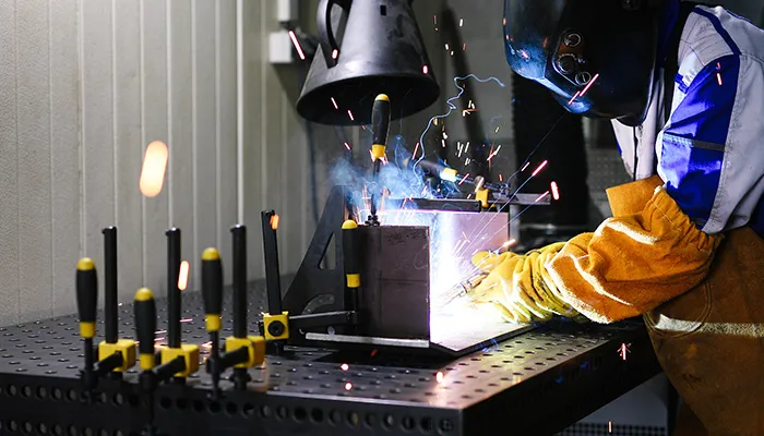
Successful prototype machining begins before material enters the machine. CAD models define the geometry, but the drawing communicates information such as tolerances, datums, threads, surface requirements, and other engineering conditions.
The first step should be identifying which features are critical to the prototype’s purpose. These may include bearing bores, alignment holes, mating faces, sealing surfaces, threaded interfaces, shaft diameters, or positional relationships.
Manufacturability should also be reviewed. Deep narrow pockets, inaccessible internal corners, extremely thin walls, long unsupported features, and unnecessarily restrictive tolerances can make machining less stable without improving prototype performance.
A CNC machining prototype creates an opportunity to evaluate these issues physically. If a feature is difficult to manufacture during the prototype stage, that information can help improve the design before the manufacturing process becomes more established.
Choosing Materials for Prototype Machining
Material selection depends on what the prototype needs to demonstrate. If the goal is primarily dimensional and assembly verification, engineers may select a material that provides appropriate machining behavior while representing the structure of the final design. If the prototype will undergo functional testing, the intended production material may be more important.
Aluminum is widely used for prototype housings, brackets, plates, fixtures, and structural components because it can support detailed machining and lightweight designs. Stainless steel may be selected where strength and corrosion resistance matter, while carbon steel is relevant to many shafts, machinery components, and structural parts.
Titanium may be used when high strength-to-weight performance or specific environmental resistance is required. Engineering plastics such as POM, nylon, or PEEK may be appropriate for electrical, low-friction, insulating, lightweight, or specialized mechanical applications.
The correct material should therefore be chosen according to the engineering question being tested rather than simply following a default prototype material.
Planning Prototype Tolerances
One of the most common mistakes in prototype development is applying unnecessarily restrictive tolerances to every dimension. A drawing may contain many features, but usually only a smaller group directly controls fit, alignment, sealing, movement, or assembly.
Prototype tolerances should reflect these functional priorities. A bearing seat may need close dimensional control, while an external clearance surface may tolerate significantly more variation without affecting performance.
This distinction helps the prototype provide better engineering information. When inspection identifies a dimensional issue, engineers can immediately understand whether it affects actual part function or only a non-critical feature.
Tolerance planning also influences machining sequence. Critical bores, datums, mating surfaces, and geometric relationships may need to be finished only after roughing has removed most residual material and the component has reached a more stable condition.
Datum Strategy Matters From the First Prototype
Datums establish how dimensions and geometric relationships are controlled. Poor datum selection can create problems not only in machining but also during inspection and assembly.
A prototype should ideally reference surfaces that reflect how the final component functions within the assembly. If several holes must align with another component, the datum structure should make that relationship clear.
Changing references repeatedly between machining setups can introduce accumulated variation. The process should therefore minimize unnecessary datum transfers when practical.
This is particularly important for multi-sided parts. A component with features on several faces may benefit from four-axis, five-axis, or horizontal machining because more geometry can be completed while maintaining a consistent reference system.
The prototype stage is an excellent time to identify whether the drawing’s datum strategy works effectively in real manufacturing and inspection.
Machining Sequence for Prototype Parts
The machining sequence should protect the stability of the component as material is removed. Roughing typically removes the majority of excess stock while leaving material on critical surfaces for later finishing.
Semi-finishing may then establish more stable geometry while retaining a controlled finishing allowance. Final machining produces the critical dimensions and surface conditions required for evaluation.
The exact sequence varies according to part design. A thick structural plate behaves differently from a thin housing, and a short rotational part requires a different process from a long precision shaft.
For components with thin walls or large pockets, machining too much material from one side too early may cause movement. Balanced stock removal can help preserve stability.
Threads, small holes, and delicate details are also often planned later in the machining sequence so that they are not damaged during heavy material removal.
Prototyping Thin-Walled Components
Thin-wall geometry creates a particular challenge because cutting forces can temporarily deflect the workpiece. After the tool passes, the wall may spring back, resulting in uneven thickness or dimensional variation.
Fixture pressure can create a similar problem. If a thin component is forced into shape while clamped, it may appear accurate during machining but change after removal from the fixture.
A stable approach uses enough support to resist machining forces without over-constraining the part. Rough machining can leave additional material to maintain stiffness, with the final wall thickness produced during lighter finishing operations.
Tool engagement, cutting direction, tool sharpness, and machining sequence all influence the result. Intermediate measurement can also help identify movement before the remaining finishing allowance is removed.
When Multi-Axis Machining Helps Prototype Development
Complex prototypes may contain angled holes, compound surfaces, side features, deep pockets, or geometry that would otherwise require several independent setups.
Multi-axis machining can reduce the need for repeated repositioning by allowing the cutting tool to access more areas of the component while maintaining a more consistent reference system.
This can be particularly valuable during prototype development because every additional setup introduces another opportunity for alignment variation. Reducing setup transitions can improve relationships between features located on different sides of the part.
Multi-axis positioning can also allow shorter tools to reach difficult areas. Shorter tooling generally provides greater rigidity, which can improve dimensional stability and surface quality.
However, not every CNC machining prototype requires five-axis equipment. The best machine configuration is the one that produces the required geometry efficiently and reliably. Simple parts may be more appropriately produced using conventional three-axis milling or CNC turning.
Prototype CNC Turning
Many prototype components are rotational rather than prismatic. Shafts, bushings, sleeves, spacers, pins, rollers, connectors, and threaded components can often be produced efficiently through CNC turning.
During prototype turning, engineers may need to evaluate diameter fits, runout, concentricity, shoulder location, thread engagement, surface condition, or interaction with bearings and seals.
Long or slender parts require particular attention because cutting force may deflect the workpiece. Proper support and stable cutting parameters help maintain straightness and diameter consistency.
If a turned part also requires holes, flats, slots, or milled features, additional machining operations may be integrated according to the available equipment and geometry.
Prototype turning can therefore provide important information about both individual component dimensions and how rotational parts behave inside a mechanical assembly.
Surface Finish and Functional Testing
Surface finish should be treated according to function rather than appearance alone. Bearing seats, sealing surfaces, sliding areas, and precision mating faces may require controlled surface conditions because texture influences performance.
A prototype used for assembly checks may not need the same finishing level across every surface. However, if the prototype will test sealing, friction, wear, or contact behavior, the relevant surfaces should closely represent the intended final condition.
Tool condition, cutting parameters, vibration, workholding, and finishing allowance all influence the machined surface. A consistent final pass generally provides better information than attempting to create critical surfaces during aggressive roughing.
Secondary processes such as grinding may also be used when a prototype contains features that require particularly controlled flatness, roundness, dimensional accuracy, or surface condition.
Inspection Should Answer Engineering Questions
Inspection is one of the most important stages of CNC machining prototype development because the objective is not merely to state whether a part matches a drawing. Measurement should help determine whether the design works.
Critical dimensions may be checked using micrometers, bore gauges, height gauges, thread gauges, pin gauges, surface measurement equipment, or coordinate measuring systems depending on the feature.
Geometric relationships such as flatness, perpendicularity, position, concentricity, and profile may be just as important as simple linear dimensions.
Inspection data becomes more valuable when it is connected to assembly results. For example, if two parts do not align correctly, measurements can help determine whether the cause lies in hole position, datum interpretation, component deformation, or another design condition.
This turns prototype inspection into a feedback process for design improvement rather than a simple final check.
Using Prototype Feedback to Improve the Design
One of the main reasons to produce a CNC machining prototype is to learn from the physical part.
A designer may discover that a tool cannot reach a particular feature efficiently, an internal corner is unnecessarily small, a wall is more flexible than expected, a fastener is difficult to install, or two mating features do not provide enough clearance.
These findings should feed directly into the next design revision.
Sometimes the most valuable prototype result is discovering what should be simplified. A small design adjustment can improve tool access, increase component rigidity, reduce unnecessary setups, or create a clearer inspection reference.
Prototype machining therefore connects CAD design with manufacturing reality. Each physical part can provide information that is difficult to fully predict from a digital model alone.
Moving From Prototype to Small-Batch Production
A successful prototype does not automatically mean the manufacturing process is ready for repeated production. The next stage should verify whether the machining sequence, fixture strategy, tooling, inspection method, and critical dimensions remain stable across multiple components.
This is where small-batch machining becomes useful. Instead of evaluating only whether one component can be made correctly, engineers can observe whether the process repeatedly produces the same important features.
Tool wear begins to matter more at this stage. Fixture repeatability and inspection consistency also become easier to evaluate.
Data collected across several components can reveal dimensional trends that are difficult to see from a single prototype. These observations can then guide process adjustments before production volumes increase.
Prototype Machining Across Different Industries
CNC machining prototypes are relevant across many engineering sectors because most mechanical products benefit from physical validation before the design is fully established.
Aerospace prototypes may focus on lightweight structures, complex geometry, precision interfaces, and high-performance materials. Automotive development may involve shafts, brackets, housings, drivetrain components, fixtures, and test assemblies.
Medical device development can involve small precision components, specialized materials, controlled surfaces, and complex assembly relationships. Industrial automation projects frequently require custom brackets, machine interfaces, mounting plates, housings, shafts, and other low-volume components during equipment development.
Real manufacturing examples can also help engineers understand how geometry, materials, machining methods, and inspection interact in different applications. Apex’s machining case studies illustrate several types of precision components across aerospace, automotive, machinery, medical, automation, and hydraulic applications.
Common CNC Machining Prototype Mistakes
A prototype can lose much of its engineering value when its purpose is not clearly defined. Trying to validate appearance, dimensional accuracy, material behavior, assembly, and every final surface condition with one uncontrolled prototype can make results difficult to interpret.
Another common problem is assigning restrictive tolerances without identifying which dimensions are truly functional. This can distract attention from the features that matter most.
Ignoring fixture behavior is also risky. A component that is forced into position during machining may not retain the same geometry after unclamping.
Designers should also avoid treating the first physical part as the final answer. The prototype exists to reveal opportunities for improvement. Discovering a design issue during prototype testing is useful information because it allows the problem to be corrected before the manufacturing process becomes less flexible.
How to Prepare a CNC Machining Prototype Drawing
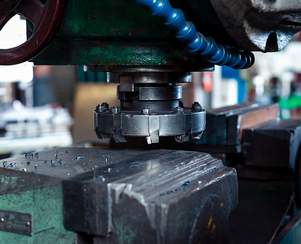
A useful prototype drawing should clearly communicate material, critical dimensions, datums, threads, surface requirements, geometric tolerances, and any features that directly influence the intended test.
Not every dimension needs the same level of control. Functional features should be identified so machining and inspection efforts remain aligned with the prototype objective.
The drawing should also agree with the CAD model. Conflicting information between two sources can create unnecessary uncertainty during manufacturing.
If a specific surface must remain unmarked, a feature must be inspected in a particular way, or the prototype will interact with another critical assembly component, those requirements should be communicated clearly.
Good technical documentation reduces interpretation and makes prototype feedback more useful.
Conclusion
A CNC machining prototype provides a practical bridge between digital design and real mechanical performance. By producing a physical component from an engineering material, designers can evaluate dimensional accuracy, assembly fit, surface conditions, structural features, machining accessibility, and functional behavior before the manufacturing process is fully established.
The most effective prototype projects begin with a clear engineering objective. Material selection, tolerance strategy, datum structure, machining sequence, workholding, finishing, and inspection should all support that objective.
Prototype machining is also an opportunity to improve the design itself. Difficult tool access, thin-wall deformation, unnecessary tolerances, unclear datums, or assembly conflicts can be identified and corrected while changes are still practical.
When prototype results are carried into small-batch validation, engineers can also evaluate repeatability, fixture stability, tool behavior, and inspection consistency. In this way, CNC machining prototype development does more than create an early part; it helps establish a more reliable path from CAD design to functional manufacturing.
FAQ
What is a CNC machining prototype?
A CNC machining prototype is a machined component produced to evaluate a design before the manufacturing process is fully established. It can be used to verify geometry, material behavior, assembly fit, tolerances, surface conditions, or functional performance.
What materials can be used for CNC machining prototypes?
Common materials include aluminum, stainless steel, carbon steel, titanium, copper, POM, nylon, PEEK, and other metals or engineering plastics. Material selection should reflect what the prototype needs to test.
Is CNC machining suitable for functional prototypes?
Yes. CNC machining is particularly useful for functional prototypes because parts can be produced from engineering materials with controlled dimensions and real mechanical interfaces. This allows evaluation of fits, threads, bearings, mounting geometry, sealing features, and structural characteristics.
Why are tolerances important in prototype machining?
Tolerances determine how much dimensional variation is acceptable. Prototype drawings should place the greatest attention on dimensions that control assembly, movement, alignment, sealing, or other functional relationships rather than applying unnecessarily restrictive limits to every feature.
What should happen after a CNC machining prototype is validated?
After the prototype confirms the main design requirements, a small-batch stage can help evaluate process repeatability, workholding stability, tool behavior, inspection methods, and dimensional consistency across multiple components before production expands.

Latest News
Contact Us
FAQ
What types of parts can be machined?
We can machine a wide range of high-precision CNC parts for automotive, aerospace, medical devices, industrial machinery, and automation equipment, including complex geometries and custom non-standard parts.
What is the machining accuracy?
We can achieve high-precision machining with ±0.005mm tolerance and ensure consistent quality through our strict quality control system.
Can you provide small-batch and prototype manufacturing services?
Yes, we support small-batch production and prototype machining, with flexible scheduling to meet urgent client requirements.
Do you offer customized processing solutions?
Yes, we provide customized solutions with one-on-one technical support, from design review and process optimization to final machining.
How long does delivery usually take?
Delivery time depends on part complexity and quantity, typically within 1-6 weeks. We provide a detailed schedule upon order confirmation.
What certifications are available for quality management systems?
We hold ISO 9001, ISO 14001, and ISO 45001 certifications, strictly following international quality, environmental, and safety standards.
How long does delivery usually take?
Delivery time depends on part complexity and quantity, typically within 1-6 weeks. We provide a detailed schedule upon order confirmation.