
How to Design CNC Machining Parts for Accuracy and Manufacturability
Home
/
Blog
/
How to Design CNC Machining Parts for Accuracy and Manufacturability
How to Design CNC Machining Parts for Accuracy and Manufacturability
August 19, 2026
Table of Contents
Introduction
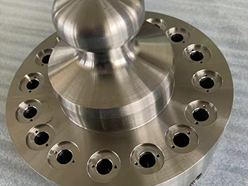
CNC machining parts can appear straightforward in a CAD model but become considerably more complex once the design reaches production. A housing may contain only a few pockets and holes, while a shaft may seem to consist mainly of stepped diameters. Yet material behavior, tool access, workholding, tolerance relationships, surface requirements and inspection methods can all determine whether the component is straightforward to manufacture or difficult to control consistently.
Good CNC part design therefore involves more than creating geometry that a machine can physically cut. The design should allow the required features to be produced accurately, measured reliably and repeated across multiple components without depending on constant manual correction.
For engineers and product developers, the key question is not simply whether a part can be machined. It is whether the part can be machined in a stable process while protecting the features that actually matter to assembly and performance.
Understanding this distinction can improve communication between design and manufacturing teams, reduce avoidable complexity and make CNC machining parts more suitable for both prototype development and repeatable production.
What Makes CNC Machining Parts Different?
CNC machining is a subtractive manufacturing method in which cutting tools remove material from a workpiece according to programmed machine movements. The broader principle of computer numerical control allows machine motion and manufacturing operations to be controlled through numerical instructions.
For CNC machining parts, however, machine programming is only one part of the process. Cutting tools have physical diameters and lengths. Workpieces must be clamped. Materials respond differently to cutting forces and heat. A component may also need to be repositioned several times before every feature can be reached.
These physical conditions explain why two CAD models with similar overall dimensions can require very different manufacturing strategies.
A part with open features and clear tool access may be comparatively straightforward to produce. Another part with deep cavities, thin walls, tightly related holes and features on several faces may require more complex fixturing, additional setups and more careful inspection.
Precision therefore comes from the complete manufacturing system rather than the CNC machine alone. Machine condition, tool selection, process planning, workholding, material consistency and measurement all contribute to the final result.
Start CNC Machining Parts Design With Function
The design process should begin by identifying what each important feature actually does.
A bore may locate a bearing. A machined face may position another assembly. A hole pattern may control the relationship between several connected components. A sealing surface may require both dimensional control and an appropriate surface condition.
These features deserve greater attention than geometry that exists mainly for clearance, appearance or material removal.
One common design problem is applying similarly demanding tolerances across almost every dimension. This can make the drawing look precise, but it does not necessarily make the component more functional. In practice, precision should be concentrated where dimensional variation would affect fit, movement, alignment, sealing or assembly.
Functional datums are especially important. They establish the surfaces, axes or features from which other critical geometry is controlled. When datums reflect the way the component actually interacts with surrounding parts, machining and inspection can use the same design logic.
For example, if several mounting holes must maintain a precise relationship with a central locating bore, their position relative to that bore may matter more than their distance from a non-functional outer edge.
This functional approach makes CNC machining parts easier to understand from both engineering and manufacturing perspectives.
Choose Materials Based on Machining and Performance
Material selection affects both how a CNC component performs and how it behaves during machining.
Aluminum alloys are commonly considered when weight, machinability and corrosion resistance are important. Stainless steels may be selected for applications requiring corrosion resistance and particular mechanical characteristics. Carbon and alloy steels can provide strength and wear-related properties, while engineering plastics may be appropriate where low weight, electrical insulation or chemical compatibility is important.
The machining strategy changes with the material.
A relatively hard material can increase cutting-tool loading. A softer or less rigid material may require additional attention when thin sections are being machined. Materials with different thermal characteristics can also respond differently as heat is generated during cutting.
Raw material condition matters as well. Bar, plate, casting and forging can each introduce different machining considerations even when the finished component has the same dimensions.
For this reason, material should not be selected solely from a finished-product perspective. Designers should also consider how the chosen material will be held, cut, finished and inspected.
Changing material late in a project may affect more than cutting parameters. It can influence wall stability, thread design, surface finishing and dimensional behavior.
The strongest or most technically advanced material is not automatically the best choice. The most appropriate material is the one that satisfies the actual operating requirements while supporting a stable manufacturing process.
Design Tolerances Around Functional Requirements
Tolerance decisions strongly influence the manufacturability of CNC machining parts.
Every machining process contains variation. Tolerances define the amount of variation that can be accepted while still allowing the component to perform correctly.
A bearing seat, locating diameter or sealing interface may require close dimensional control because a relatively small variation could affect function. By contrast, a clearance surface or non-critical outer dimension may allow a wider tolerance without changing how the assembly works.
The challenge becomes greater when several dimensions interact. Even if each individual dimension falls within its specified range, accumulated variation can still affect the position or fit of the final assembly.
This is where geometric dimensioning and tolerancing can be particularly useful. Controls such as position, flatness, perpendicularity and runout can describe functional relationships that may not be communicated clearly through independent linear dimensions alone.
A practical tolerance review should therefore ask what each requirement protects.
If changing a tolerance slightly would not affect assembly, movement, sealing, positioning or service performance, there may be little functional reason for making that dimension more restrictive.
The relationship between design requirements and manufacturing capability is also discussed in Apex’s existing guide to CNC machining tolerances, which can support a broader tolerance strategy for precision components.
Good tolerance design is not about requesting the tightest possible values. It is about defining the correct level of control for the function of the part.
Geometry Rules That Improve CNC Manufacturability
Geometry has a direct influence on tool selection, machining time, setup planning and process stability.
CAD software allows designers to create extremely small radii, narrow slots, deep cavities and thin walls without considering the limitations of physical cutting tools. Manufacturing must deal with those limitations.
Design for manufacturability helps connect digital geometry with the actual behavior of tools and workpieces.
Internal Corners, Cavities and Tool Access
Rotating milling tools are cylindrical, which means they naturally leave a radius in an internal corner. An extremely small internal radius can force the manufacturer to use a smaller cutting tool.
Smaller tools may provide access to detailed features, but they can also be less rigid and more sensitive to demanding cutting conditions.
When the corner radius is not functionally critical, a more practical radius generally provides greater flexibility in tooling and machining strategy.
Deep pockets create a different challenge. The cutter must reach the required depth while the tool holder remains clear of surrounding material. As the cutting tool extends farther from the holder, rigidity becomes increasingly important.
A pocket should therefore be evaluated in terms of both width and depth. A feature that appears wide enough from a top view can still create difficult machining conditions if it extends deeply into the component.
Tool approach direction should also be considered. Side holes, undercuts and internal features may require different orientations or specialized tooling depending on where they are positioned.
Thin Walls and Deep Features
Thin walls are frequently required in lightweight housings, covers and precision structures, but they can move under cutting forces.
As surrounding material is removed, the remaining wall becomes less rigid. The cutting tool may then push the wall slightly away from its nominal position, affecting thickness, flatness or surface condition.
Deep narrow ribs, slender shafts and other high-aspect-ratio features can create similar problems.
This does not mean such geometry should always be avoided. When the feature is functionally necessary, the machining process can be designed around it. Material may be removed in stages, additional support may be used, or the machining sequence may be adjusted to preserve rigidity for as long as possible.
The important point is that wall thickness and feature depth should not be considered independently of material, unsupported length and machining direction.
How CNC Milling and Turning Affect Part Design
The primary geometry of a component can often indicate which CNC process should play the leading role.
Turning is naturally suited to rotational CNC machining parts. Shafts, sleeves, bushings, rollers, threaded components and similar parts can often be organized around a central axis, allowing several important features to be created while the workpiece rotates.
Milling is generally better suited to prismatic geometry such as housings, brackets, plates, pockets, slots and complex surfaces.
Some components combine both types of geometry. A turned body may include cross holes, flats or milled pockets, while a milled housing may contain precision bores and cylindrical features requiring additional operations.
In these cases, the manufacturing route should be considered before the design is finalized.
If several critical cylindrical features should remain concentric, designing them around a common turning axis can improve process logic. If multiple holes and surfaces have strong positional relationships, placing them so they can be machined from a common orientation may reduce unnecessary repositioning.
Multi-axis machining expands what can be reached without repeatedly removing and re-clamping the workpiece. This is valuable for complex CNC machining parts, but advanced equipment should not become an excuse for unnecessary design complexity.
The strongest design normally works with the natural strengths of the machining process.
Reduce Setups Without Compromising Part Function
A machining setup begins when a workpiece is positioned, located and clamped for an operation. If the part must be turned or repositioned to reach another face, a new setup or orientation may be required.
Additional setups are sometimes unavoidable. A complex component may contain features that cannot physically be reached from one direction.
The objective is therefore not to eliminate every setup but to eliminate unnecessary ones.
Consider a rectangular component containing several critical holes on one surface and a single non-critical feature on the opposite side. If that secondary feature could be relocated without changing product function, the overall machining route might become simpler.
Setup planning becomes even more important when tightly related features are involved.
If several holes must maintain accurate positional relationships, machining them under the same reference condition may reduce the number of times the relationship must be re-established.
Workholding also needs to be considered. A part can contain individually machinable features yet remain difficult to manufacture because every convenient clamping surface is removed too early in the process.
Manufacturing sequence should therefore influence geometry decisions. Leaving suitable reference or clamping surfaces available during earlier operations can make later machining more stable.
Surface Finish and Secondary Processing Considerations
Dimensional tolerance and surface finish describe different characteristics.
A surface can satisfy its dimensional requirement while still having a texture that is unsuitable for sealing, sliding or another functional purpose. The reverse is also possible: a visually smooth surface may not meet the dimensional relationship required by the assembly.
Surface finish should therefore be specified according to function.
Bearing areas, sealing surfaces and sliding interfaces may need more deliberate surface requirements than hidden clearance surfaces.
Cutting strategy, material, tool geometry and feed conditions all affect the machined surface. Some CNC machining parts may also require secondary operations after milling or turning.
Grinding can be used where specific dimensional or surface requirements justify an additional finishing process. Deburring can remove unwanted sharp edges or burrs. Other finishing operations may modify appearance, corrosion behavior or wear characteristics depending on the application.
Secondary processing can also alter dimensions. If a later operation removes or adds material, the machining plan should account for that change rather than treating finishing as a completely separate step.
Surface requirements should therefore be included in manufacturing planning from the beginning.
Quality Control for CNC Machining Parts
Inspection is most effective when it reflects the function of the component.
Simple dimensions can often be verified with standard measuring equipment, while complex geometric relationships may require more advanced measurement methods.
The measurement method must also be capable of resolving the requirement being checked. A tight specification is of limited value if it cannot be measured reliably using an appropriate inspection process.
This means inspection planning should begin before the component is completed.
Some critical features may be easier to inspect during an intermediate machining stage. Once additional geometry is added, access may become restricted.
In-process inspection can also help identify tool wear, fixture movement or gradual process variation before these issues affect a larger number of parts.
The following table summarizes how common design decisions influence CNC manufacturability:
| Design Area | Manufacturing Concern | Practical Approach |
|---|---|---|
| Material | Cutting behavior and stability | Match material to function and machining conditions |
| Tolerances | Process and inspection difficulty | Tighten only function-critical features |
| Internal corners | Cutter size and rigidity | Use practical radii where possible |
| Deep cavities | Tool reach and deflection | Avoid unnecessary depth |
| Thin walls | Part movement during cutting | Maintain suitable support and machining sequence |
| Feature orientation | Setup requirements | Group related features around practical directions |
| Datums | Repeatable positioning | Use functional reference features |
| Surface finish | Tooling and secondary processes | Specify according to actual function |
| Workholding | Part stability | Preserve suitable locating and clamping surfaces |
| Inspection | Measurement accessibility | Design critical features so they can be verified |
Quality control also becomes more important when moving from prototypes to repeated production. Producing one acceptable component demonstrates that the geometry is achievable. Stable production requires the process to continue creating acceptable results over time.
Material consistency, fixture repeatability, tool condition and documented inspection criteria therefore become part of the quality system for CNC machining parts.
Common Design Mistakes That Make CNC Parts Difficult to Produce
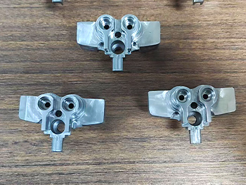
One frequent problem is over-tolerancing.
When almost every drawing dimension is assigned a demanding tolerance, the manufacturer has less flexibility even though many of those dimensions may have little effect on function. Inspection also becomes more extensive.
Another common issue is an unnecessarily small internal radius. If the geometry does not require that radius for assembly or performance, it may simply restrict cutter selection.
Deep narrow pockets can create similar difficulties because longer cutting tools are less rigid. Very thin walls can also become unstable as surrounding material is removed.
Feature placement can create hidden complexity as well.
A single hole on an otherwise unused face may require another setup. Several non-critical features positioned in different directions can turn a relatively simple component into a multi-orientation machining project.
Designers sometimes overlook workholding completely. A component may be easy to model but difficult to clamp once early machining operations have removed its original reference surfaces.
Another issue is specifying unnecessarily deep threads. Thread engagement should correspond to the mechanical requirement of the joint rather than automatically extending through the maximum available depth.
Inspection access should also be reviewed. A feature that is technically machinable but difficult to measure can create uncertainty during quality control.
These are not machine limitations in the narrow sense. They are design-manufacturing interface problems, which is why early DFM review can provide significant value.
From Prototype to Repeatable Production
Prototype machining provides an opportunity to understand how CNC machining parts behave before the process is standardized.
During early production, the machining team may discover that a particular feature needs additional support, a tool path creates unnecessary vibration or a tolerance relationship should be inspected earlier in the sequence.
These observations should not remain informal operator knowledge.
Before repeat production, successful prototype conditions should be translated into a stable manufacturing process. Workholding methods should be repeatable. Cutting tools and operation sequences should be defined. Inspection points should correspond to critical drawing characteristics.
Features that are particularly sensitive to tool wear or setup variation should also be identified.
This difference between prototype success and production stability is important. A skilled machinist may be able to make one difficult component through careful adjustment, but repeated production should not depend on continuous improvisation.
Early components therefore provide manufacturing feedback as well as physical parts.
When lessons from prototype machining are incorporated into programming, fixturing, inspection and drawing revisions, future CNC machining parts become more predictable to manufacture.
How to Evaluate a CNC Machining Parts Manufacturer
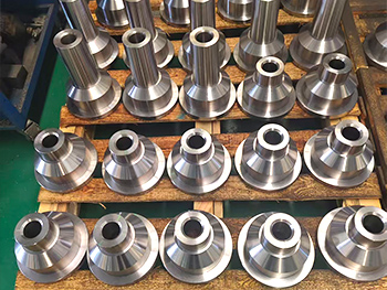
Selecting a manufacturer should involve more than reviewing a machine list.
The supplier should be able to interpret drawings, understand tolerance relationships and identify geometry that may create manufacturing or inspection risks.
Equipment capability remains important. Rotational components require suitable turning capacity, while complex multi-face components may benefit from advanced milling or multi-axis machining.
However, machine capability is only useful when combined with process planning.
A manufacturer providing integrated CNC machining services should be able to consider turning, milling, multi-axis operations and related secondary processes as parts of one manufacturing route.
Quality capability deserves the same attention. Measuring equipment does not automatically create reliable quality. Inspection should be connected to functional drawing requirements and process feedback.
Technical communication can also reveal manufacturing experience.
If a drawing contains a difficult-to-reach pocket, an unnecessary tolerance or a feature likely to create unstable workholding, the supplier should be able to explain why the feature creates risk and discuss possible manufacturing solutions.
For complex CNC machining parts, this engineering collaboration can be as important as the machining equipment itself.
Conclusion
Successful CNC machining parts begin with design decisions that reflect real manufacturing conditions.
Accuracy is not created simply by assigning tight tolerances, and manufacturability is not guaranteed by using advanced CNC equipment. Stable results depend on the interaction between geometry, material, tooling, workholding, machining sequence, surface requirements and inspection.
A strong design identifies which dimensions and relationships are functionally important. It uses practical internal radii where possible, considers tool access before deep features are finalized and avoids unnecessary setups created by non-critical feature placement.
It also considers how the component will be measured.
These decisions are particularly important when the design moves from prototype development into repeatable production. What can be produced once through careful adjustment should eventually become a controlled process that can produce consistent results repeatedly.
The objective of design for manufacturability is not to remove necessary complexity. It is to make functional complexity practical to manufacture while eliminating geometry and specifications that provide little engineering value.
When design and production planning are considered together, CNC machining parts become easier to machine accurately, easier to inspect and more suitable for reliable manufacturing.
FAQ
What are CNC machining parts?
CNC machining parts are components created by computer-controlled machine tools that remove material from a solid workpiece. They can include shafts, housings, brackets, precision interfaces and complex multi-axis components. Their final accuracy depends on design, material, tooling, workholding and inspection.
What materials can be used for CNC machining parts?
CNC machining parts can be produced from many metals and engineering plastics. Material selection should consider strength, weight, corrosion resistance, operating environment and machining behavior. The most suitable material is one that meets functional requirements while supporting a stable manufacturing process.
How should tolerances be selected for CNC machining parts?
Tolerances should reflect the actual function of each feature. Dimensions controlling fits, alignment, sealing or movement may require closer control, while non-critical geometry can often use more practical tolerances. This approach supports reliable machining without adding unnecessary manufacturing complexity.
How can CNC machining parts be made easier to manufacture?
Designers can improve manufacturability by providing practical internal radii, sufficient tool access, stable wall thicknesses, clear functional datums and sensible feature orientations. Workholding, machining sequence and inspection access should also be considered before the final drawing is released.
What should be checked before CNC machining parts enter production?
Before production, confirm material specifications, critical tolerances, datums, surface requirements, threads, edge conditions and secondary processes. Tool access, workholding and inspection methods should also be reviewed so potential manufacturing problems can be identified before machining begins.
Latest News
Contact Us
FAQ
What types of parts can be machined?
We can machine a wide range of high-precision CNC parts for automotive, aerospace, medical devices, industrial machinery, and automation equipment, including complex geometries and custom non-standard parts.
What is the machining accuracy?
We can achieve high-precision machining with ±0.005mm tolerance and ensure consistent quality through our strict quality control system.
Can you provide small-batch and prototype manufacturing services?
Yes, we support small-batch production and prototype machining, with flexible scheduling to meet urgent client requirements.
Do you offer customized processing solutions?
Yes, we provide customized solutions with one-on-one technical support, from design review and process optimization to final machining.
How long does delivery usually take?
Delivery time depends on part complexity and quantity, typically within 1-6 weeks. We provide a detailed schedule upon order confirmation.
What certifications are available for quality management systems?
We hold ISO 9001, ISO 14001, and ISO 45001 certifications, strictly following international quality, environmental, and safety standards.
How long does delivery usually take?
Delivery time depends on part complexity and quantity, typically within 1-6 weeks. We provide a detailed schedule upon order confirmation.