
What Is a CNC Lathe Machine and How Does It Produce Precision Parts?
Home
/
Blog
/
What Is a CNC Lathe Machine and How Does It Produce Precision Parts?
What Is a CNC Lathe Machine and How Does It Produce Precision Parts?
August 19, 2026
Table of Contents
Introduction
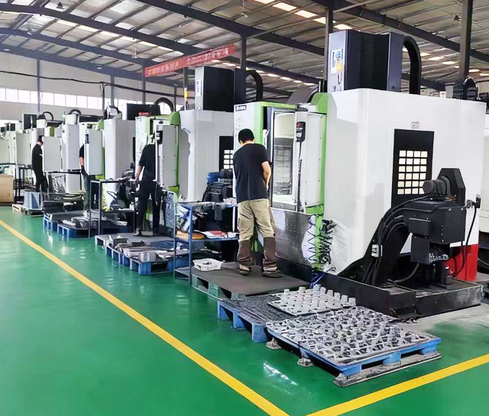
A CNC lathe machine is one of the most important machine tools for producing components built around a rotational axis. Shafts, pins, bushings, sleeves, rollers, threaded parts, flanges and many other cylindrical components can be manufactured by rotating a workpiece while controlled cutting tools remove material from its surface.
What makes modern CNC turning different from conventional manual lathe work is not simply automation. The machine combines programmed motion, spindle control, tooling, workholding and process parameters into a repeatable machining system. Once a stable process has been developed, the same sequence of operations can be applied consistently across multiple workpieces.
However, a CNC lathe machine should not be viewed as a machine that automatically guarantees precision. Part accuracy still depends on material behavior, workholding, cutting tools, tool wear, machine condition, thermal effects, programming and inspection. A technically advanced lathe can still produce inconsistent parts if these factors are poorly controlled.
For engineers and manufacturers, understanding how a CNC lathe machine actually works makes it easier to design turned components, select suitable materials, plan tolerances and determine whether turning is the right process for a particular part.
What Is a CNC Lathe Machine?
A CNC lathe machine is a computer-controlled machine tool designed primarily to remove material from a rotating workpiece. During a typical turning operation, the workpiece is held by a chuck or another workholding device and rotates around the spindle axis while a cutting tool moves along programmed paths.
This basic relationship between the rotating workpiece and the cutting tool defines the turning process. External diameters can be reduced, internal holes can be bored, faces can be machined, grooves can be produced and threads can be formed depending on the tooling and machine configuration.
The CNC system controls movements according to programmed instructions. Rather than manually moving a cutting tool throughout the complete operation, the machining program defines tool positions, cutting paths, spindle conditions and related movements.
This makes the CNC lathe machine particularly suitable when a component contains repeatable cylindrical geometry. Once the part is correctly programmed and the manufacturing process is stable, important features can be produced according to the same machining sequence from one workpiece to the next.
The important point is that CNC turning combines digital control with physical machining. Software determines where the tool should move, but the final result still depends on how the cutting tool interacts with the real material.
How Does a CNC Lathe Machine Work?
The machining cycle begins with a workpiece that is positioned and secured in the machine. Depending on the component, the starting material may be bar stock, tube, a pre-machined blank, a forging, a casting or another suitable workpiece form.
Once the material is held correctly, the spindle rotates the workpiece. Cutting tools mounted on a tool turret or related toolholding system are brought into controlled contact with the rotating material.
The CNC program determines the movement of the cutting tool. During external turning, the tool removes material from the outside diameter. During facing, the tool moves across the end of the component. Boring enlarges or finishes an internal diameter, while grooving creates narrower recessed features. Threading requires coordinated movement between tool position and spindle rotation.
A single CNC lathe machine may therefore complete several different operations without removing the workpiece between every feature.
This ability is especially valuable when several diameters, shoulders, grooves and threads share the same rotational axis. Machining related features under the same workholding condition can help preserve their geometric relationship.
Programming is only one stage of this workflow. Tool offsets must be established, the workpiece reference must be defined, suitable cutting conditions must be selected and the finished component must be measured against the drawing.
For this reason, CNC turning should be understood as a controlled manufacturing process rather than simply automated cutting.
Core Components of a CNC Lathe Machine
The spindle is central to the operation of a CNC lathe machine because it rotates the workpiece. Spindle behavior influences cutting conditions, surface quality and the stability of the machining process.
The chuck or other workholding device connects the workpiece to the spindle. Reliable workholding is essential because the component must remain securely positioned while cutting forces act on it. The method selected depends on part geometry, material, length and the surfaces available for gripping.
A tool turret allows multiple cutting tools to be prepared for different operations. Instead of manually replacing a tool for each machining step, the machine can index the required tool into position according to the program.
Linear axes control tool movement relative to the rotating workpiece. The exact machine architecture can vary, but these controlled movements allow the tool to produce diameters, lengths, faces, tapers, grooves and other features.
The tailstock or other support systems may be used when a long workpiece requires additional stability. Without suitable support, a slender component may deflect during machining, affecting dimensions and surface condition.
Coolant and chip-management systems also contribute to process stability. Machining removes material continuously, so chips must be controlled and cutting conditions managed to prevent them from interfering with the tool, component or subsequent operations.
These systems work together. Precision turning is rarely the result of one machine component operating independently; it comes from the coordinated behavior of the complete machining system.
What Operations Can a CNC Lathe Machine Perform?
Turning is the primary operation, but a CNC lathe machine can perform several types of material removal during a complete machining cycle.
External turning reduces and shapes outside diameters. It may create straight cylindrical sections, shoulders, tapers or stepped profiles depending on the part design.
Facing machines the end of the workpiece and is commonly used to establish a controlled surface from which axial dimensions can be referenced.
Boring works on an existing internal opening. It can enlarge the diameter, improve geometry or produce a specific internal feature. Drilling may also be incorporated into the machining sequence where machine configuration allows.
Grooving produces narrow recesses on external or internal surfaces. These features can be required for retaining rings, sealing elements, clearance or other functional purposes.
Threading creates screw threads according to the required geometry. External and internal threads may both be produced depending on the component and available tooling.
Parting separates a completed component from bar material or divides the workpiece at a defined position.
Some advanced turning centers add driven tooling and additional controlled axes. This expands the range of features that can be produced without transferring the part to a separate milling machine. However, whether these capabilities are necessary should depend on part geometry rather than equipment complexity alone.
Which Parts Are Best Suited to CNC Lathe Machining?
A CNC lathe machine is naturally suited to parts whose geometry is organized around a central axis.
Shafts are a typical example. They may contain several diameters, shoulders, grooves, threads and bearing interfaces that can be produced while the component rotates around one primary centerline.
Bushings and sleeves also fit this process well because their internal and external diameters usually have an important relationship. Machining these features under carefully planned setups can support concentric geometry.
Pins, spacers, couplings, nozzles, rollers and many flange-type components can also be strong candidates for CNC turning.
Part suitability should not be judged by overall shape alone. The relationship between features is equally important. A component containing a large number of flat pockets and features spread across several faces may be better suited to CNC milling, even if it also includes one cylindrical section.
Conversely, a primarily cylindrical component with only a few secondary milled features may still be best treated as a turned part with additional machining afterward.
A useful design question is therefore: Which axis controls most of the functional geometry?
If several important surfaces and diameters share one rotational axis, a CNC lathe machine is often a logical starting point for process planning.
Materials Used for CNC Lathe Machine Processing
CNC turning can be applied to many engineering metals and plastics, but material behavior has a direct effect on tooling and process strategy.
Aluminum alloys are frequently selected when relatively low weight and good machinability are useful. Various steels are used when strength, wear resistance or structural performance is important, while stainless steels are suitable for many components requiring corrosion-related performance and particular mechanical properties.
Engineering plastics can also be turned when their characteristics suit the final application. However, they do not behave exactly like metals during cutting, and factors such as rigidity, heat generation and clamping pressure need to be considered.
The same CNC lathe machine cannot necessarily use identical cutting conditions for every material.
Tool material, insert geometry, spindle speed, feed, depth of cut and coolant strategy may all change according to workpiece material and the required result. More information about common CNC machining materials can help establish material selection before detailed process planning begins.
Material condition can also influence turning behavior. Two components with identical finished geometry may require different strategies when one begins as bar stock and another begins as a near-net-shape blank.
The material decision should therefore connect part performance with manufacturing requirements. Selecting a material first and considering machinability later can create avoidable difficulties, particularly when the design contains slender features, deep bores or demanding surface requirements.
What Controls CNC Lathe Machine Accuracy?
Accuracy is produced by the entire process rather than by the CNC controller alone.
The machine must first have sufficient mechanical stability for the component being produced. The spindle, guides, toolholding and axis positioning all contribute to how reliably programmed motion is converted into actual material removal.
Workholding is equally important. If the component is not located consistently, subsequent machining cannot reliably reproduce the same geometry. Excessive or inappropriate clamping can also affect certain workpieces, especially relatively thin or flexible components.
Tool condition introduces another source of variation. Cutting edges gradually wear as they machine material. Wear can change cutting forces, dimensions and surface condition, so tool life should be considered when developing a repeatable process.
Thermal behavior also matters. The workpiece, cutting tool and machine can all experience temperature changes during machining. The effect may be small for some parts but more important when dimensions and geometric relationships are closely controlled.
The workpiece itself can deflect under cutting forces. This is particularly relevant for long shafts and slender parts. Even when the programmed tool position is correct, a flexible workpiece can move away from the tool during cutting.
Finally, inspection must be suitable for the required tolerance. Precision is difficult to control if the measurement system cannot reliably identify the variation that manufacturing needs to manage.
| Accuracy Factor | Possible Effect | Process Consideration |
|---|---|---|
| Workholding | Positioning error or deformation | Use stable locating and suitable clamping |
| Tool wear | Dimensional drift and finish changes | Monitor tool condition and offsets |
| Workpiece rigidity | Deflection during cutting | Support slender or flexible components |
| Material behavior | Different cutting response | Adjust tooling and machining parameters |
| Thermal conditions | Dimensional variation | Maintain a stable machining process |
| Programming | Incorrect geometry or tool path | Verify programs and setup references |
| Spindle condition | Runout or unstable cutting | Maintain appropriate machine condition |
| Inspection | Unrecognized process variation | Match measurement method to requirement |
This relationship explains why two facilities using similar equipment may achieve different results. The machine creates capability, but process control determines how effectively that capability is used.
CNC Lathe Machine Tooling and Cutting Strategy
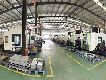
Cutting tools are the physical interface between the CNC lathe machine and the workpiece. Their geometry and condition have a direct effect on how material is removed.
Different tools are used for external turning, boring, grooving, threading and parting. Tool selection depends on the feature being produced as well as material, workpiece rigidity and surface requirements.
Roughing and finishing should also be considered separately.
Roughing removes larger amounts of material and establishes the approximate geometry. The primary objective is usually stable material removal while leaving sufficient allowance for later operations.
Finishing uses lighter, more controlled cuts to establish final dimensions and surface condition. Separating these objectives can make the process easier to control than expecting one tool path to accomplish everything simultaneously.
Cutting conditions should also reflect workpiece geometry. A thick, rigid component can respond differently from a long slender shaft even when both are made from the same material.
Internal machining introduces additional considerations because boring tools extend into the workpiece. The farther a boring bar extends from its support, the more important rigidity becomes. Poor stability can contribute to vibration, inconsistent dimensions and unsuitable surface condition.
Tooling strategy therefore needs to be developed around the individual component rather than selected according to the machine model alone.
CNC Lathe Machine vs CNC Milling
CNC turning and CNC milling both use programmed machine motion to remove material, but they approach the workpiece differently.
On a CNC lathe machine, the workpiece normally provides the primary rotation while the cutting tool moves relative to it. This arrangement naturally produces cylindrical and rotational features.
In CNC milling, the cutting tool usually provides the primary cutting rotation while the workpiece is held in a fixture. Milling is therefore naturally suited to flat surfaces, pockets, slots and complex prismatic geometry.
Neither process is universally more precise or more advanced. Their suitability depends on part design.
A shaft containing several concentric diameters is naturally suited to turning. A rectangular housing with pockets and hole patterns is more naturally suited to milling.
Many real industrial components combine both types of features. In these situations, the manufacturer may use turning and milling as complementary processes rather than treating them as alternatives.
Modern manufacturing planning should therefore begin with geometry and function. The objective is not to choose the most complex machine, but to choose a process route that can establish important features accurately and repeatably.
How Workholding Affects CNC Turning Results
Workholding is sometimes treated as a secondary setup detail, but it has a major influence on CNC lathe machine performance.
The component must be held strongly enough to resist machining forces, yet the clamping method should not damage or unnecessarily distort the workpiece.
Short and rigid parts can often be supported effectively near the chuck. Long components behave differently because the unsupported section may flex as cutting tools apply force.
Additional support may therefore be required for slender workpieces. The correct approach depends on diameter, length, material and machining operations.
The location of gripping surfaces also matters.
If a finished critical surface must be clamped for a later operation, the manufacturer needs to consider how the clamping method may affect that surface. In some cases, machining allowances or alternative locating surfaces can make the process more stable.
Part designers can improve manufacturability by considering how the blank will be held during each major operation.
A component that has no practical locating or gripping surfaces can be difficult to manufacture even when its individual features are straightforward to machine.
Good CNC turning design therefore considers both cutting access and workholding access.
Surface Finish, Tolerance and Inspection
Surface finish and dimensional accuracy are related but separate requirements.
A turned diameter can fall within dimensional tolerance while having a surface condition that is unsuitable for its intended function. This can matter for bearing seats, sealing areas, sliding interfaces or visible finished surfaces.
Cutting tool geometry, feed, spindle conditions, material behavior and machine stability can all influence the surface produced during turning.
Tolerance should also be specified according to function.
Not every dimension on a turned component needs the same degree of control. A bearing diameter or locating shoulder may need close attention, while an unrelated clearance surface may not require equivalent precision.
Concentricity and runout-related relationships can be particularly important in rotational components. When several functional diameters share the same axis, manufacturing and inspection should consider their relationship rather than treating each diameter as an isolated measurement.
Measurement should be planned around the drawing requirement. External diameters, internal bores, lengths, threads and geometric relationships may require different inspection approaches.
A robust CNC lathe machine process therefore connects the drawing, machining strategy and measurement method from the beginning rather than waiting until the finished part reaches final inspection.
Common CNC Lathe Machine Problems and Their Causes
Chatter is one of the more recognizable turning problems. It appears when vibration develops between the cutting system and the workpiece, potentially affecting surface condition and process stability.
The cause may involve tooling, workpiece support, cutting conditions or a combination of factors. Simply changing one machine setting without identifying the underlying source may not provide a stable solution.
Dimensional variation can result from tool wear, workpiece movement, thermal changes, inconsistent workholding or unsuitable process parameters.
Poor surface condition may also have several possible causes. Cutting edges can deteriorate, chips can interfere with the process, vibration may occur or the selected cutting conditions may not match the material and feature.
Long slender components introduce another common problem: deflection. The cutting tool applies force to the rotating workpiece, and a flexible section can move away from its intended position.
Chip control can also affect production stability. Chips should be removed from the cutting zone rather than accumulating around the tool and workpiece.
The important lesson is that CNC turning problems should be diagnosed as process problems. Adjusting the program may help in some cases, but other cases require changes to tooling, workholding, material preparation or operation sequence.
From Prototype Turning to Repeatable Production
Producing the first acceptable turned component proves that the design can be manufactured. It does not automatically prove that the process is ready for repeated production.
Prototype machining is an opportunity to identify sensitive features.
A long shaft may need additional support. A deep internal bore may require a different tool strategy. A particular diameter may respond noticeably to tool wear, while another feature may remain stable throughout the machining cycle.
These observations should be incorporated into the production process.
Stable workholding methods, tool selection, offsets, operation sequence and inspection points should be documented so that repeat production does not depend on rediscovering the same solution for every batch.
This is one of the advantages of working with an integrated provider of CNC turning services. Turning requirements can be considered together with boring, threading, drilling and related machining operations when the component requires more than a simple external profile.
Repeatability is ultimately a process characteristic. Advanced equipment provides the capability, but documentation, tooling control, inspection and manufacturing experience convert that capability into consistent parts.
How to Determine Whether a CNC Lathe Machine Is Right for Your Part
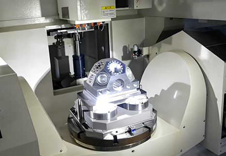
The first consideration should be geometry.
If most important features are cylindrical and organized around a common centerline, CNC turning is likely to be a strong manufacturing option. Shafts, sleeves, bushings, pins and rotational components are typical examples.
The second consideration is feature relationship.
Turning becomes particularly useful when several diameters, shoulders or threaded features must maintain a controlled relationship around the same axis.
Part length and rigidity should also be evaluated. Very long or slender components may still be turned successfully, but support and process planning become more important.
Material and surface requirements influence the decision as well. The material must be suitable for the required machining strategy, while final dimensional and surface requirements should be achievable with an appropriate process route.
Finally, consider whether significant non-rotational geometry is present.
A small number of secondary holes or flats does not necessarily make a component unsuitable for turning. However, a design dominated by pockets, complex surfaces and features on many faces may be more naturally treated as a milling component.
The most effective process selection starts from the finished part rather than from the equipment available.
Conclusion
A CNC lathe machine is much more than an automated version of a conventional lathe. It combines programmed control, spindle rotation, cutting tools, workholding and process planning to manufacture repeatable rotational components.
Its natural strength lies in producing shafts, pins, bushings, sleeves, rollers, threaded components and other parts whose important geometry shares a rotational axis.
However, precision does not come from CNC control alone. Material behavior, tool condition, workholding stability, workpiece rigidity, thermal effects and inspection all influence the finished result.
Engineers can improve CNC turning outcomes by designing around functional geometry, applying tolerances where they are genuinely required and considering how the component will be held and measured during manufacturing.
For manufacturers, a reliable process requires the same systems-level approach. Programming, tooling, setup and quality control should work together rather than being managed as separate stages.
When part design and process planning are aligned, a CNC lathe machine can provide a stable foundation for producing accurate, repeatable and functionally reliable turned components.
FAQ
What is a CNC lathe machine used for?
A CNC lathe machine is mainly used to manufacture components with rotational geometry, including shafts, pins, bushings, sleeves, rollers, flanges and threaded parts. The workpiece rotates while programmed cutting tools create external diameters, internal bores, faces, grooves and other features.
How does a CNC lathe machine differ from a manual lathe?
A CNC lathe machine follows programmed instructions to control tool movement and machining operations, while a manual lathe depends more directly on operator-controlled movements. CNC control is particularly useful when the same geometry must be reproduced consistently across multiple components.
What materials can a CNC lathe machine process?
A CNC lathe machine can process many engineering metals and plastics when suitable tooling and cutting conditions are selected. Material properties influence spindle conditions, feed, tool geometry, workholding and heat management, so the machining strategy should be developed for the actual workpiece material.
What parts are best suited to a CNC lathe machine?
Parts with cylindrical geometry and features arranged around a common rotational axis are particularly suitable. Typical examples include shafts, bushings, sleeves, pins, rollers and threaded components. Parts dominated by flat surfaces, pockets and multi-face geometry may require more milling operations.
What affects CNC lathe machine accuracy?
CNC lathe machine accuracy depends on machine condition, workholding, cutting-tool wear, material behavior, workpiece rigidity, thermal conditions, programming and inspection. A stable process controls these factors together rather than relying on programmed tool position alone to achieve consistent dimensions.
Latest News
Contact Us
FAQ
What types of parts can be machined?
We can machine a wide range of high-precision CNC parts for automotive, aerospace, medical devices, industrial machinery, and automation equipment, including complex geometries and custom non-standard parts.
What is the machining accuracy?
We can achieve high-precision machining with ±0.005mm tolerance and ensure consistent quality through our strict quality control system.
Can you provide small-batch and prototype manufacturing services?
Yes, we support small-batch production and prototype machining, with flexible scheduling to meet urgent client requirements.
Do you offer customized processing solutions?
Yes, we provide customized solutions with one-on-one technical support, from design review and process optimization to final machining.
How long does delivery usually take?
Delivery time depends on part complexity and quantity, typically within 1-6 weeks. We provide a detailed schedule upon order confirmation.
What certifications are available for quality management systems?
We hold ISO 9001, ISO 14001, and ISO 45001 certifications, strictly following international quality, environmental, and safety standards.
How long does delivery usually take?
Delivery time depends on part complexity and quantity, typically within 1-6 weeks. We provide a detailed schedule upon order confirmation.