7 Cast Aluminum Design Factors That Improve Part Quality
Home
/
Blog
/
7 Cast Aluminum Design Factors That Improve Part Quality
7 Cast Aluminum Design Factors That Improve Part Quality
August 19, 2026
Table of Contents
Introduction
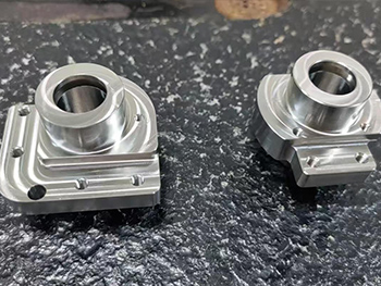
Cast aluminum is widely used when a component needs a combination of relatively low weight, complex geometry, corrosion resistance and the ability to integrate multiple features into a single metal part. Housings, covers, brackets, supports, equipment bodies and other engineered components can often be formed closer to their final geometry through casting than by removing all material from a solid block.
However, obtaining a useful cast aluminum component involves much more than filling a mold with molten metal. Alloy behavior, wall thickness, metal flow, cooling, shrinkage, internal porosity, machining allowances and functional tolerances all influence the final result. A casting can look acceptable externally while still creating problems when critical bores, sealing faces or mounting features are machined later.
This is why cast aluminum parts should be designed as complete manufacturing systems. Casting establishes the near-net shape, while machining, inspection and finishing often establish the functional characteristics required by the final assembly.
The following seven factors help explain where cast aluminum quality is created and why early cooperation between part design, casting and precision machining can prevent many problems before production begins.
1. Select Cast Aluminum Alloys Around the Real Application
All cast aluminum is not the same. Different alloy families contain different combinations of aluminum and alloying elements, producing variations in castability, mechanical behavior, corrosion resistance, thermal characteristics and response to subsequent processing.
The appropriate alloy should therefore be selected according to how the finished component will function rather than according to a generic preference for aluminum.
A housing exposed to mechanical loading has different priorities from a cover whose primary function is protection. A component that must transfer heat may emphasize thermal behavior, while another part may require better dimensional stability or corrosion resistance.
The casting process itself also influences alloy selection. An alloy suitable for one casting method may not provide the same processing behavior under another combination of filling pressure, mold material and cooling conditions.
The broader family of aluminum alloys includes compositions developed for different manufacturing and performance requirements. Designers should therefore specify the required material condition clearly instead of describing the component only as “aluminum.”
Material selection also affects later CNC machining. Cutting behavior, chip formation, tool loading and achievable surface condition can vary between aluminum alloys. If critical surfaces will be machined after casting, alloy selection should consider both casting performance and machining requirements.
A practical specification begins with operating conditions and works backward toward material choice. This provides a stronger engineering basis than choosing an alloy first and attempting to adapt the component around it afterward.
2. Design Wall Thickness for Stable Metal Flow and Cooling
Wall thickness is one of the most influential characteristics of a cast aluminum design.
Molten metal must travel through the mold before solidifying. Extremely thin or abrupt sections can make this flow more difficult to control, while large variations in thickness can cause different regions of the component to cool at different rates.
Uniform wall thickness is therefore generally a useful design objective where product function permits it.
This does not mean every section must have exactly the same thickness. Structural requirements, mounting features and load paths can require local changes. The goal is to make transitions deliberate rather than abrupt.
For example, a large thick section connected immediately to a much thinner wall can create uneven thermal behavior. A smoother transition can make solidification more predictable and may reduce the risk of localized casting problems.
Designers should also distinguish between thickness required for structural performance and thickness added simply because the component “looks stronger.” Adding unnecessary material can change cooling behavior without providing meaningful functional improvement.
Ribs are often a useful alternative when local stiffness is required. Instead of increasing the thickness of an entire wall, properly designed reinforcing features can support the structure while keeping the casting geometry more balanced.
The best wall strategy therefore considers stiffness, metal flow, cooling and later machining simultaneously.
3. Understand How Geometry Affects Cast Aluminum Quality
One of the main advantages of cast aluminum is the ability to create geometry that would require extensive material removal if machined completely from solid stock. Complex external forms, ribs, bosses, cavities and integrated mounting features can often be incorporated directly into the casting.
That freedom should still be used carefully.
Sharp transitions, isolated heavy sections, difficult internal passages and poorly positioned bosses can affect how metal enters and solidifies within the mold. A geometry that is technically possible may not be the most stable geometry for repeated manufacturing.
Fillets and radiused transitions can be important where abrupt intersections would otherwise concentrate material and create sudden changes in section thickness. They can also reduce sharp corners that complicate mold filling.
Bosses used for threaded holes or mounting points deserve particular attention. Their diameter, height and connection to surrounding walls should be considered together. A very heavy boss connected to a relatively thin wall may behave differently during cooling from the surrounding material.
Ribs should also have a clear structural purpose. Excessive reinforcement can produce a part that is heavier and thermally less uniform without providing proportional improvement in stiffness.
A useful design review therefore looks beyond the outside shape. Engineers should consider how every rib, cavity, boss and transition affects the path and volume of molten metal throughout the part.
4. Control Shrinkage, Porosity and Other Casting Risks
Casting involves a transition from liquid metal to a solid component. That physical change creates manufacturing conditions that do not exist in subtractive machining.
Shrinkage occurs as the metal cools and solidifies. The casting process and mold design need to account for this behavior so that the finished geometry approaches the intended dimensions after cooling.
Porosity is another important consideration. Gas or solidification-related voids may occur within a casting depending on material preparation, mold filling, thermal behavior and process control.
The practical significance of porosity depends heavily on where it occurs and what the component needs to do.
A small internal discontinuity located within a non-critical region may have a different engineering consequence from porosity exposed during machining of a sealing face or located close to a highly loaded feature.
This distinction demonstrates why quality acceptance should be related to function rather than appearance alone.
Other possible casting concerns include incomplete filling, inclusions, surface irregularities and dimensional changes. Their causes can differ, so a single corrective action should not be expected to solve every problem.
A more useful approach is to connect the observed condition to material preparation, mold design, filling behavior, cooling and part geometry. Repeated defects in the same area often indicate a systematic relationship between the component and the process rather than random variation.
For critical cast aluminum parts, inspection planning should therefore identify which regions have the greatest functional importance before determining appropriate acceptance criteria.
5. Add Machining Allowance Where Precision Actually Matters
Casting is highly effective for creating near-net shapes, but many engineered cast aluminum components still require CNC machining.
Mounting faces may need controlled flatness. Bearing bores may require dimensional accuracy. Threaded holes, sealing surfaces, locating features and mating interfaces may need tighter control than the casting process alone is intended to provide.
This creates an important design question: which surfaces should remain as-cast, and which should be machined?
Machining every surface usually provides little engineering benefit. Instead, machining should focus on features whose dimensions, geometry or surface condition directly influence function.
Adequate machining allowance must be considered on these surfaces. If too little material remains, normal casting variation may leave insufficient stock to establish the final feature consistently. Excessive allowance, however, increases the amount of material that must later be removed and can unnecessarily complicate processing.
Datums should also be considered before machining begins.
The first machining operation needs reliable reference surfaces or locating features. If the casting does not provide a stable way to position the workpiece, subsequent operations may become difficult to control.
This relationship is particularly important when CNC machining services are used as post-processing for cast components. Casting and machining should be planned together so that allowances, locating features and critical dimensions support the same finished-part requirements.
A strong cast aluminum design therefore distinguishes three groups of surfaces: geometry that can remain as-cast, geometry that must be machined, and reference features required to make that machining repeatable.
6. Set Tolerances According to Casting and Machining Functions
Tolerance strategy for cast aluminum components should reflect the manufacturing process used to create each feature.
As-cast dimensions and CNC-machined dimensions should not automatically be treated as though they come from the same process. Their functional roles and manufacturing controls can be different.
A general external contour that provides clearance may tolerate more dimensional variation than a machined bearing bore. Similarly, an as-cast rib used mainly for stiffness usually does not need the same level of dimensional control as a machined locating face.
This distinction should be communicated clearly on engineering drawings.
Applying unnecessarily restrictive tolerances to non-functional casting geometry can make quality evaluation more complicated without improving the assembled product. The better approach is to identify the dimensions that actually control fit, motion, sealing, alignment and structural performance.
Machined features should then be related to meaningful datums.
Imagine a cast housing containing a precision bore and several mounting holes. If those features control the position of another assembly, their relationship to each other may be more important than the exact position of a non-functional exterior casting surface.
Tolerance planning should reflect that functional hierarchy.
Inspection should follow the same logic. Critical machined geometry may require direct dimensional verification, while general casting features can be evaluated according to the level of control appropriate to their purpose.
This prevents a common manufacturing mistake: demanding precision everywhere instead of controlling precision where it produces measurable functional value.
7. Plan Quality Control Across Casting and Post-Machining
Cast aluminum quality should not be evaluated only at the end of production.
Once material has been machined away, some information about the original casting condition may become more difficult to observe. Conversely, machining can expose internal areas that were not visible on the original casting.
A staged inspection strategy is therefore more useful.
Incoming or pre-machining inspection can evaluate overall casting condition, key dimensions and features that affect workholding. Intermediate checks can confirm whether machining is progressing from stable reference surfaces. Final inspection then verifies the dimensions, geometry and surfaces that determine assembly performance.
The exact methods should match the risks associated with the component. Visual examination can identify obvious surface conditions. Dimensional inspection evaluates geometry. Other inspection techniques may be appropriate where internal integrity is important to the application.
The table below summarizes how several cast aluminum design decisions influence downstream manufacturing.
| Design Area | Main Manufacturing Risk | Practical Engineering Approach |
|---|---|---|
| Alloy selection | Unsuitable material or processing behavior | Match alloy characteristics to function and manufacturing |
| Wall thickness | Uneven filling or cooling | Maintain balanced sections where practical |
| Heavy transitions | Localized thermal differences | Use gradual transitions and purposeful reinforcement |
| Bosses and ribs | Concentrated material sections | Design features around structural need and casting behavior |
| Casting variation | Insufficient machining stock | Provide appropriate machining allowance |
| Datum strategy | Unstable machining setup | Create practical locating and reference features |
| Tolerances | Unnecessary process restrictions | Separate functional machined tolerances from general cast geometry |
| Internal integrity | Hidden discontinuities | Apply inspection according to functional risk |
| Surface requirements | Unnecessary finishing operations | Machine or finish only where function requires it |
| Final inspection | Missed dimensional relationships | Inspect according to drawing function and assembly needs |
The main lesson is that casting quality cannot be separated completely from machining quality. If the component will ultimately contain precision-machined interfaces, both stages contribute to whether the final part performs correctly.
Cast Aluminum and CNC Machining Work Best as One Process Plan
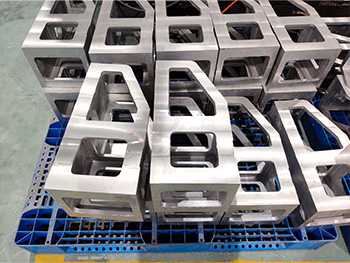
Casting and CNC machining are sometimes treated as separate sourcing activities, but complex components often benefit from viewing them as consecutive stages of one manufacturing route.
Casting is efficient at establishing the broad form of a component. CNC machining is effective at establishing selected high-precision geometry.
Used together, these processes allow designers to place precision where it is required without machining every feature from solid material.
The challenge is the interface between the two processes.
A casting needs enough machining stock in the correct locations. The workpiece must have reliable surfaces or features for initial location. Machining should not unexpectedly expose defects in function-critical areas, and the final datum strategy needs to remain compatible with the part drawing.
Apex’s existing aluminum casting process guide discusses the broader relationship between aluminum casting methods, tolerances and subsequent processing. For a manufacturing project, that relationship should ideally be considered before the casting geometry is finalized.
This is especially relevant for housings, brackets, support bodies and equipment components containing both complex cast surfaces and accurate machined interfaces.
The design team should identify early which dimensions originate from the casting and which will ultimately be established during machining. Doing so makes both the casting drawing and the final machining drawing more useful.
Surface Requirements for Cast Aluminum Parts
Not every cast aluminum surface needs additional finishing.
Some surfaces can remain in their original cast condition when their texture and dimensional characteristics do not affect function. Other areas may require machining because they contact another component, establish a seal, locate an assembly or support movement.
The specification should distinguish these requirements.
Surface finishing can also serve purposes beyond dimensional accuracy. Depending on component requirements and compatible material conditions, later processes may be used to alter surface appearance, corrosion behavior or wear characteristics.
However, finishing should not be specified without understanding how it interacts with the underlying casting.
A surface treatment cannot correct poor dimensional geometry, and cosmetic processing cannot compensate for inappropriate material or casting design.
Similarly, machining a surface does not automatically eliminate every casting-related issue. If internal porosity exists close to the machined region, removing material may reveal it.
The most reliable approach is therefore to establish the required final surface condition first and then determine which combination of casting, machining and finishing should create it.
Cast Aluminum vs Machining From Solid Material
Cast aluminum and machining from solid aluminum should not be treated as competing processes in every situation. They solve different manufacturing problems.
Machining directly from solid stock offers considerable control over geometry and is especially useful for prototypes, relatively simple components and parts where much of the final geometry requires precision machining.
Casting becomes particularly attractive from a manufacturing perspective when the component contains complex near-net geometry, integrated ribs, cavities, bosses or structural forms that would otherwise require extensive material removal.
The decision should begin with the part rather than a general preference for one process.
A highly complex housing may benefit from casting followed by targeted machining. A smaller precision block with extensive machining on nearly every surface may not gain the same manufacturing advantage from a cast preform.
Production consistency also matters. Once a cast component is introduced into a machining process, casting variation becomes an input variable that machining engineers need to understand.
This is why the most useful comparison is not simply “casting versus machining.” A better question is how much geometry should be established by each process.
For many engineered components, the optimal answer is a combination: casting produces the efficient near-net form, while machining establishes the functional precision.
Common Cast Aluminum Design Mistakes
One common mistake is designing the component as though casting produces exactly the same geometry as a finished CNC operation.
This can lead to overly restrictive dimensions on non-critical surfaces or insufficient allowance around areas that require later machining.
Another problem is making abrupt changes in wall thickness without considering cooling behavior. Large local concentrations of metal can respond differently from surrounding thin sections during solidification.
Poorly integrated bosses and ribs can create similar issues. Reinforcing features should support the load path and casting geometry rather than simply adding material wherever additional strength is assumed to be useful.
Designers may also overlook machining access. A bore may require precision finishing but be positioned in a way that makes tool access or workholding unnecessarily difficult.
Datum strategy is another frequent issue. If the casting does not provide stable features from which the first machining operation can locate the part, the manufacturing team must create an alternative setup strategy.
Over-specification should also be avoided. Requiring machined-level accuracy on every external casting surface can add inspection complexity without improving functional performance.
Finally, casting and machining drawings should not contradict each other. The manufacturing route should clearly communicate which geometry is established during casting and which dimensions control the finished component.
These mistakes are most effectively corrected before tooling and production planning are finalized.
From Prototype Castings to Repeatable Production
A prototype cast aluminum component provides information about much more than whether the design can be physically produced.
Early parts can reveal how wall transitions behave, whether intended machining allowances are sufficient, how easily the casting can be located for CNC operations and whether the proposed inspection strategy captures the important functional characteristics.
That information should be incorporated into production planning.
If one region repeatedly requires excessive machining adjustment, the underlying casting design or allowance should be reviewed. If workholding is unstable, additional locating features may need to be considered. If machining exposes recurring internal discontinuities in the same location, the relationship between casting conditions and part geometry deserves investigation.
The objective is to convert lessons from early production into a repeatable manufacturing process rather than relying indefinitely on operator compensation.
Fixture design, machining programs, inspection plans and incoming casting criteria can all be refined based on actual manufacturing observations.
This feedback loop is particularly valuable for cast aluminum because the component passes through several transformations before it becomes a finished precision part.
Manufacturing experience should therefore influence subsequent design revisions. The most mature cast component is rarely the one that simply matches the original CAD model; it is the one whose design has been refined around actual process behavior without compromising its intended function.
How to Evaluate a Cast Aluminum Manufacturing Solution
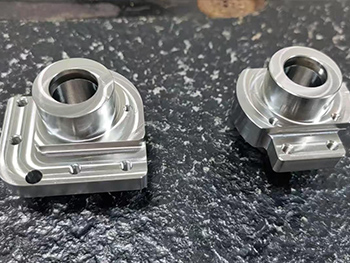
A suitable manufacturing solution should be evaluated according to the complete component rather than the casting operation alone.
Material knowledge is important because alloy selection influences both casting and downstream processing. Casting design capability matters because wall thickness, transitions, bosses and other features affect manufacturing behavior.
Post-processing capability becomes equally important when the component contains precision surfaces.
If a cast housing requires bearing bores, threaded holes and controlled mounting faces, the final quality depends on how casting and machining are coordinated. A supplier that understands only one stage may have difficulty optimizing the complete process route.
Inspection capability should also correspond to actual component risks. The manufacturer should understand which characteristics must be evaluated before machining and which are best verified on the final part.
Technical communication provides another useful indication of manufacturing maturity. If a component contains difficult wall transitions, insufficient machining stock or unclear datums, the engineering team should be able to identify these issues during review rather than waiting until final inspection.
The best cast aluminum solution is therefore not defined simply by the ability to produce a casting. It should provide a controlled route from raw material and near-net geometry through precision machining and final verification.
Conclusion
Cast aluminum provides designers with significant geometric flexibility, but successful components require more than selecting aluminum and choosing a casting process.
Alloy selection, wall thickness, geometry, solidification behavior, machining allowance, tolerances and quality control all influence the final result. These factors become even more important when the casting contains precision-machined interfaces.
The strongest manufacturing strategy divides responsibility between processes intelligently.
Casting should establish the complex near-net geometry that it produces effectively. CNC machining should establish the dimensions, bores, faces, threads and interfaces that require greater functional precision. Inspection should verify the characteristics that actually determine assembly and performance.
This approach also improves design decisions. Instead of demanding maximum precision throughout the entire component, engineers can concentrate precision where it creates functional value.
For complex cast aluminum parts, early coordination between casting, machining and inspection is therefore one of the most useful ways to improve repeatability. A casting designed with downstream manufacturing in mind is easier to locate, easier to machine and easier to evaluate as a finished component.
FAQ
What is cast aluminum?
Cast aluminum is aluminum or an aluminum alloy formed by introducing molten metal into a mold and allowing it to solidify into a defined shape. The resulting component may remain largely as-cast or undergo CNC machining, inspection and surface finishing when tighter functional requirements are needed.
Is cast aluminum suitable for precision components?
Yes, cast aluminum can be used for precision components when casting and post-machining are planned together. The casting can establish complex near-net geometry, while CNC machining creates critical bores, mounting faces, threads and other features that require closer dimensional or geometric control.
Can cast aluminum parts be CNC machined?
Yes. CNC machining is frequently used to finish functional areas of cast aluminum parts. Designers should provide suitable machining allowance and stable reference features so critical surfaces can be produced consistently without removing unnecessary material from non-functional areas of the casting.
What causes defects in cast aluminum parts?
Casting conditions involving metal flow, solidification, material preparation, mold design and component geometry can contribute to defects. Porosity, incomplete filling and dimensional variation should be evaluated according to where they occur and whether they affect strength, sealing, machining or final assembly.
How should cast aluminum parts be designed for machining?
Cast aluminum parts intended for machining should include sufficient stock around critical surfaces, accessible machining features and practical locating references. Functional tolerances should focus on finished interfaces, while general as-cast geometry should use requirements appropriate to the casting process.
Latest News
Contact Us
FAQ
What types of parts can be machined?
We can machine a wide range of high-precision CNC parts for automotive, aerospace, medical devices, industrial machinery, and automation equipment, including complex geometries and custom non-standard parts.
What is the machining accuracy?
We can achieve high-precision machining with ±0.005mm tolerance and ensure consistent quality through our strict quality control system.
Can you provide small-batch and prototype manufacturing services?
Yes, we support small-batch production and prototype machining, with flexible scheduling to meet urgent client requirements.
Do you offer customized processing solutions?
Yes, we provide customized solutions with one-on-one technical support, from design review and process optimization to final machining.
How long does delivery usually take?
Delivery time depends on part complexity and quantity, typically within 1-6 weeks. We provide a detailed schedule upon order confirmation.
What certifications are available for quality management systems?
We hold ISO 9001, ISO 14001, and ISO 45001 certifications, strictly following international quality, environmental, and safety standards.
How long does delivery usually take?
Delivery time depends on part complexity and quantity, typically within 1-6 weeks. We provide a detailed schedule upon order confirmation.