Custom Welding for Complex Metal Parts: Design, Quality and Production
Home
/
Blog
/
Custom Welding for Complex Metal Parts: Design, Quality and Production
Custom Welding for Complex Metal Parts: Design, Quality and Production
August 19, 2026
Table of Contents
Introduction
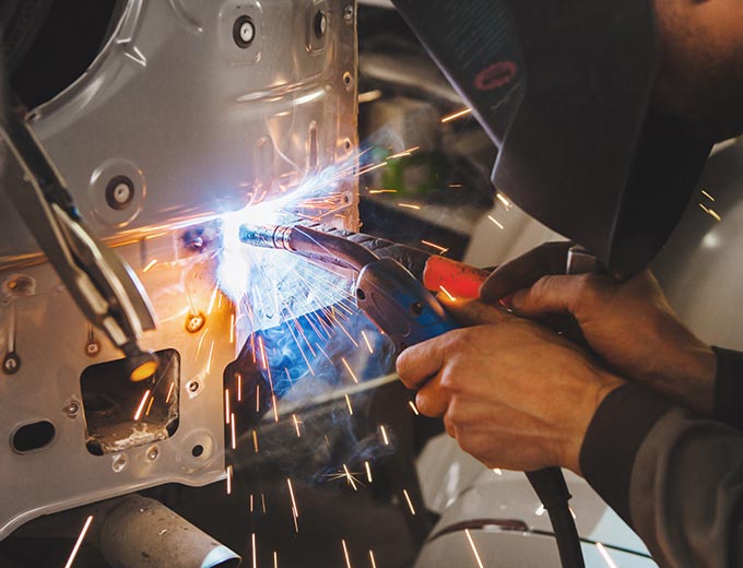
Custom welding becomes important when a metal assembly cannot be treated as a standard fabrication job. The material may be unusual, the geometry may contain difficult access areas, the welded structure may need to maintain alignment with machined features, or the finished assembly may need a specific combination of strength, dimensional stability and surface quality.
In these situations, welding is only one stage of the manufacturing process. Joint design, material condition, fit-up, heat input, welding sequence, fixturing, distortion control, post-weld machining and inspection all influence the final result.
This is what separates custom welding from a simple “join these two pieces” approach. A custom project begins with the functional requirements of the completed component and works backward toward the welding process.
For designers and manufacturing engineers, this distinction matters because a weld can be structurally sound while the surrounding assembly is dimensionally unsuitable. Excessive thermal movement can shift mounting surfaces, change hole alignment or create additional machining requirements. Poor joint accessibility can make an otherwise reasonable design difficult to produce consistently.
A well-developed custom welding process therefore treats the welded assembly as a complete engineered component. The objective is not only to create a strong joint, but also to maintain the geometry, consistency and functional characteristics required after welding is complete.
What Is Custom Welding?
Custom welding is a manufacturing approach in which the welding process is adapted to the specific material, joint geometry, component dimensions and functional requirements of an individual part or assembly.
It may involve TIG, MIG, arc welding or another suitable joining process depending on the project. The broader concept of welding covers joining methods that create coalescence between materials through heat, pressure or a combination of process conditions.
What makes custom welding different is the level of process adaptation.
A standard welded bracket may use an established joint and repeatable sequence with limited engineering changes. A custom assembly may require a unique fixture, several joint types, different welding positions and a carefully planned sequence to control dimensional movement.
The component may also need machining before or after welding.
For example, mating edges may be machined before assembly to improve fit-up. After welding, mounting faces, bores or locating features may require CNC machining to restore or establish final geometry.
This interaction between welding and machining is particularly important for precision components.
Custom welding should therefore be understood as a coordinated production method rather than a single welding operation. Material preparation, assembly, welding, inspection and secondary processing should all support the same final engineering requirements.
Why Custom Welding Begins With the Part Design
Many welding problems originate in the component design rather than at the welding station.
Joint position determines whether the torch can reach the weld area. Material thickness influences how heat moves through the assembly. Feature location affects whether the component can be clamped securely. The relationship between welded and machined surfaces determines how much distortion can be tolerated.
For this reason, design review should take place before the welding route is finalized.
One of the first questions should be which dimensions are functionally critical after welding.
A structural frame may need two mounting faces to remain aligned. A welded housing may contain a bore that must maintain a specific relationship to an external bracket. A fabricated machine component may require several holes to line up with another assembly.
These relationships deserve more attention than dimensions that have little effect on final function.
Designers should also consider whether some geometry should be produced before welding or afterward. A precision hole located close to a major weld may be difficult to protect from thermal movement. In some cases, leaving that feature unfinished until after welding creates a more stable manufacturing route.
Custom welding is therefore strongest when design intent and process sequence are developed together.
Material Selection Changes the Custom Welding Strategy
Different materials respond differently to welding heat.
Thermal conductivity, expansion behavior, alloy composition, surface condition and thickness all affect how a joint should be prepared and welded. A process that performs reliably on one material cannot automatically be transferred to another.
Carbon steels are commonly welded in fabricated mechanical structures, but their exact condition and thickness still influence joint preparation and process settings.
Stainless steel requires careful control of heat and cleanliness, particularly where surface condition and corrosion-related performance are important.
Aluminum behaves differently because of its thermal characteristics and surface oxide. Preparation, joint cleanliness and process stability become especially important.
Material combinations can create additional challenges. Joining different metals may involve differences in melting behavior, thermal expansion and metallurgical compatibility. Such applications require a process developed around the actual material pair rather than general welding assumptions.
Thickness also changes the welding strategy.
A thick structural section can absorb and distribute heat differently from a thin sheet or wall. Thin components can be more sensitive to distortion, while thick joints may require greater attention to penetration and joint preparation.
Custom welding therefore starts with accurate material identification. The drawing should clearly define the relevant material rather than leaving the welding team to infer it from appearance or general component type.
Choosing the Right Custom Welding Process
There is no single welding process that is automatically best for every custom component.
TIG welding provides controlled heat input and precise weld-pool management, which can make it useful for detailed joints, thin sections and applications where localized control is important.
MIG welding can be effective where productive deposition and repeatable welding of appropriate structural components are required.
Conventional arc welding processes may remain practical for heavier structures and particular joint conditions.
Process selection should be based on the component rather than a preference for one welding technology.
Material type, thickness, joint accessibility, weld length, penetration requirements, production conditions and final dimensional requirements should all be considered.
The appearance of the weld is also only one part of the decision. A visually smooth weld may not provide the required penetration or dimensional stability, while a structurally effective weld does not necessarily need to look highly decorative if appearance is not a functional requirement.
Apex’s welded structural component processing services integrate different welding methods with structural processing and dimensional requirements. In custom work, this broader approach is useful because the selected welding process needs to fit the entire component route rather than operate as an isolated stage.
A strong process choice therefore answers three questions: Can the joint be created reliably? Can the required geometry be maintained? Can the process be repeated consistently?
Joint Design Has a Direct Effect on Weld Quality
Joint geometry determines how easily heat and filler material can reach the area that must be joined.
Butt joints, lap joints, fillet joints and other configurations create different accessibility and heat-distribution conditions. Even within the same general joint type, edge geometry and fit-up can change welding behavior significantly.
Consistent gaps are particularly important.
If one assembly has a tight joint while another contains a larger opening, the welding operator may need to change filler addition, travel behavior or heat input to compensate. This increases variation from part to part.
Joint preparation should therefore be controlled before welding begins.
The edges should be prepared according to the material thickness, process and required weld condition. Contamination, burrs and inconsistent geometry can all influence the weld pool.
Accessibility matters just as much as joint geometry.
A CAD model can place a weld deep inside a corner where the finished joint looks perfectly reasonable on screen. In production, however, the torch angle, filler access and shielding conditions may become difficult to control.
Good custom welding design leaves sufficient space for the actual process.
The best joint is not necessarily the smallest or least visible one. It is the joint that satisfies structural requirements while providing repeatable access, practical fit-up and controllable thermal behavior.
Fit-Up and Fixturing Create Repeatability Before Welding Starts
A welder cannot consistently compensate for poorly located components.
Before the welding arc begins, each part of the assembly needs to be positioned according to the intended geometry. This is the purpose of fit-up and fixturing.
Fixtures establish relationships between components and help hold those relationships while tack welding and final welding are performed.
However, more clamping force does not automatically create greater precision.
If a flexible component is forced into position and welded under heavy restraint, it may move after the clamps are released. The final geometry can therefore differ from the geometry seen while the assembly was inside the fixture.
A good fixture balances positioning with thermal behavior.
It should locate the components consistently, provide access to the weld and support the areas that need stability without unnecessarily preventing all movement.
Datum selection also matters.
If the welded assembly will later be machined, the fixture should preserve useful reference relationships whenever possible. The manufacturing team needs to know which surfaces or axes will control the final component.
Tack weld placement should be planned as part of this strategy. Tack welds establish temporary stability, but they also introduce localized heat. Their position and sequence can influence how the assembly behaves during final welding.
In custom welding, accurate fit-up is therefore not a preparation detail. It is one of the main factors controlling repeatability.
Heat Input and Distortion Control in Custom Welding
Welding introduces concentrated heat into a component. The heated material expands, while surrounding cooler material restrains that expansion. As the joint cools, contraction occurs.
This thermal cycle can change the geometry of the assembly.
The amount and direction of movement depend on material, thickness, joint design, heat input, weld length, restraint and welding sequence.
Distortion is particularly important when a welded component also contains machined surfaces.
A mounting face may move out of alignment. A long structure may develop angular change. A bore near the welded area may shift relative to another functional feature.
Preventing these problems does not mean simply using the lowest possible heat input.
Insufficient welding energy can create other quality problems. The objective is to use the appropriate energy for the joint while controlling how that heat is distributed throughout the structure.
Sequence is one of the most useful variables.
Welds can sometimes be divided into planned sections rather than being completed continuously in one direction. Welding on different sides of an assembly can also help balance thermal effects when geometry allows.
Cooling between operations may be appropriate for some components, while other applications require a controlled continuous process.
The solution depends on the individual assembly.
This is why custom welding should not rely on one universal anti-distortion technique. Thermal behavior should be considered specifically for the geometry being produced.
Welding Sequence Should Be Planned Before Production
Welding sequence determines the order in which joints are completed.
This can influence distortion, access and even whether later welds can be reached at all.
Imagine a box-shaped assembly containing several internal and external joints. If the outer structure is completely closed first, an internal joint may become difficult or impossible to access. The sequence must therefore consider both thermal behavior and physical access.
Long structures create another challenge.
Completing a long weld from one end to the other may concentrate thermal movement in a particular direction. Dividing operations or balancing welds around the component may create a more predictable result.
The location of critical geometry should also influence sequence planning.
If one side contains a machined reference surface that must remain relatively stable, the process may need to balance welding around that region differently from a non-critical area.
Sequence planning also improves repeatability between operators and production batches.
When the process exists only as individual operator preference, different assemblies may be welded in different orders. That can introduce variation even when machine settings remain the same.
For custom welding, a defined sequence turns practical welding knowledge into a repeatable manufacturing process.
Custom Welding and CNC Machining Should Be Planned Together
Complex welded components often require precision machining.
The critical question is when that machining should occur.
Some features need to be created before welding because they help locate the assembly or provide accurate reference geometry. Other features are better completed after welding because thermal distortion could otherwise change their final position.
Consider a welded machine frame with precision mounting surfaces.
The main structural members may be cut and prepared before welding. After the complete structure has been welded and stabilized, CNC machining can establish the final mounting planes and hole relationships.
A smaller welded housing may use a different sequence. Certain reference features might be machined first to support accurate assembly, while the final bore and sealing surfaces are completed after welding.
There is no universal rule that all machining should happen before or after welding.
The process should be divided according to function.
Apex’s CNC machining services can be integrated with welded components where final bores, faces, holes or other features require controlled machining. The important engineering decision is identifying which geometry should be protected through welding and which geometry should be established afterward.
When welding and machining are planned separately, unnecessary correction work can result. When they are planned together, each process can establish the features it controls most effectively.
Post-Weld Machining Restores Functional Geometry
Post-weld machining does not simply make a welded component look more precise. Its main purpose is to establish the final functional relationships required by the assembly.
Mounting faces can be milled to establish flatness and relative position. Bores can be machined to create controlled dimensions. Hole patterns can be produced from functional datums after the welded structure has reached its final condition.
This can be particularly useful for larger fabricated components.
Attempting to preserve every final dimension throughout welding may create an unnecessarily restrictive process. In some cases, it is more practical to control the welded structure within an appropriate range and then machine selected functional features afterward.
Machining allowance must therefore be included in the design.
If a surface will be finished after welding, enough material should remain to establish the required geometry. Too little allowance can make it difficult to correct normal welding movement.
Excessive allowance is also undesirable because it creates unnecessary material removal.
The amount should reflect expected process variation and the final requirement.
Post-weld machining should therefore be designed into the component rather than treated as an emergency correction for an uncontrolled welding process.
Surface Preparation Affects Custom Welding Quality
Clean material is essential for a stable welding process.
Oil, coatings, oxide, scale, moisture and other surface conditions can influence arc stability and the quality of the resulting joint. The exact preparation method depends on material and welding process.
Preparation should therefore be defined rather than left entirely to individual judgment.
Cut edges may also require attention.
Thermal cutting, sawing, machining and other upstream processes can leave different surface conditions. Burrs or irregular edges can affect fit-up, while contamination from previous processing may need to be removed.
Cleaning needs to be controlled particularly carefully when the material is sensitive to surface contamination.
Joint preparation should also avoid introducing new contaminants through inappropriate tools or handling.
The objective is to create consistent starting conditions.
If one assembly arrives clean and accurately prepared while another requires extensive adjustment at the welding station, process repeatability becomes difficult.
Custom welding quality therefore begins upstream, with material handling, cutting, edge preparation and fit-up all contributing to the condition of the joint before welding starts.
Quality Control Should Match the Function of the Welded Component
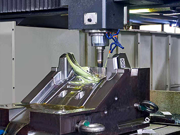
Inspection should be planned according to what the welded assembly needs to accomplish.
Visual inspection is useful for identifying surface conditions such as obvious discontinuities, irregular profiles and other visible weld characteristics.
However, visual appearance alone cannot verify every functional requirement.
Dimensional inspection may be equally important for custom welding. Mounting distances, alignment, flatness and the relationship between welded members can directly affect whether the final component assembles correctly.
Some applications may also require additional methods for evaluating weld integrity. The appropriate method depends on joint type, material, loading conditions and the type of discontinuity that needs to be detected.
The important principle is risk-based inspection.
A cosmetic cover does not necessarily require the same verification strategy as a load-bearing machine component. Likewise, a hidden weld that controls structural integrity may deserve more attention than a highly visible joint that carries little functional load.
The table below summarizes the main control areas in a custom welding project.
| Control Area | Main Question | Manufacturing Consideration |
|---|---|---|
| Material | Is the material clearly defined? | Match welding method and preparation to material behavior |
| Joint design | Can the weld be produced consistently? | Provide suitable access, edge preparation and fit-up |
| Fixture design | Can components be located repeatably? | Control geometry without unnecessary restraint |
| Heat input | Will thermal movement affect function? | Balance penetration requirements with distortion control |
| Welding sequence | In what order should joints be completed? | Manage access and thermal distribution |
| Critical dimensions | Which geometry must survive welding? | Identify features requiring protection or later machining |
| Post-weld machining | What geometry should be established afterward? | Leave suitable machining allowance and datums |
| Inspection | How will weld quality be verified? | Match inspection methods to functional risk |
| Surface preparation | Are joint conditions consistent? | Control cleaning, edge condition and contamination |
| Production repeatability | Can the same result be reproduced? | Document setup, sequence and inspection requirements |
A quality plan should therefore follow the actual function of the assembly instead of applying the same inspection routine to every welded component.
Common Custom Welding Problems and Why They Occur
Distortion is one of the most familiar welding problems because it can be observed directly in the geometry of the assembly.
However, it is only one possible issue.
Porosity, lack of fusion, undercut, cracking, inconsistent bead geometry and contamination-related problems can also occur depending on material and process conditions.
The important point is that these conditions do not all have the same cause.
Porosity may be related to shielding, contamination or material conditions. Fusion problems can involve heat input, joint access or travel technique. Dimensional movement is strongly connected to thermal distribution and structural restraint.
Corrective action should therefore begin with root-cause analysis.
Changing welding current every time a problem appears is not an effective universal solution.
The manufacturer should consider whether the issue originates from material preparation, joint dimensions, fixture condition, welding parameters, access or process sequence.
Repeated problems in the same location are particularly informative.
If distortion consistently develops around one joint, the geometry and welding sequence in that region should be reviewed. If discontinuities repeatedly appear near a difficult corner, accessibility and shielding may require attention.
A mature custom welding process uses inspection findings to improve upstream decisions rather than only repairing completed assemblies.
From Prototype Custom Welding to Repeatable Production
Prototype welded assemblies provide valuable process information.
The first component can reveal how the material responds to the planned sequence, whether the fixture provides adequate stability and where thermal movement actually occurs.
This information should be measured and documented.
If one mounting surface consistently moves after a particular weld is completed, the production team can adjust sequence, restraint or machining allowance before repeated manufacturing begins.
If fit-up requires extensive manual correction, the upstream cutting or component tolerances may need review.
The prototype stage is therefore an opportunity to validate the process, not simply the drawing.
As the project moves toward repeatable production, successful conditions should be standardized.
Fixture locations, tack sequence, welding order, major process parameters and inspection points should be defined clearly enough that the same manufacturing logic can be followed consistently.
Operator experience remains valuable, but repeat production should not depend entirely on undocumented personal technique.
The goal is to convert welding knowledge into process knowledge.
This transition is particularly important for custom welding because every project may begin with unique geometry. Once that geometry enters repeated production, however, the manufacturing process should become increasingly controlled and predictable.
Custom Welding for Small Precision Parts vs Large Structures
Custom welding requirements change significantly with component scale.
Small precision parts may be highly sensitive to localized heat because there is relatively little material available to distribute thermal energy. A small amount of movement can also become significant when nearby machined features require close alignment.
These components may require careful joint access, localized heat control and precise fixturing.
Large welded structures present different challenges.
Individual welds can be longer, structural members can accumulate thermal movement across greater distances and the completed assembly may require substantial alignment control.
Large size does not automatically mean that every dimension requires high precision. Instead, the critical interfaces should be identified.
A large frame may tolerate variation in non-functional external areas while requiring close control of a few mounting pads or shaft-support locations.
This is where welding and machining can complement each other effectively.
The structure can be fabricated around appropriate overall requirements, while selected functional surfaces are established later through precision machining.
Custom welding should therefore scale its control strategy according to the component instead of applying identical methods to every project.
How to Evaluate a Custom Welding Manufacturer
A capable custom welding manufacturer should be evaluated on engineering and process control rather than welding equipment alone.
The first capability is drawing interpretation.
The manufacturer should understand which joints carry structural responsibility, which dimensions are functionally important and which surfaces may require post-weld machining.
Material knowledge is equally important because welding strategy changes with alloy, thickness and joint configuration.
Fixture capability should also be considered.
Complex custom assemblies often need purpose-designed locating and clamping methods. A manufacturer that can develop suitable fixtures has greater control over repeatability than one relying only on manual measurement during assembly.
Integration with machining is another important consideration.
If the welded component contains precision interfaces, the ability to coordinate welding with boring, milling, drilling or grinding can simplify process planning and datum management.
Inspection capability should match the actual project requirements.
Finally, technical communication is essential.
When a drawing contains poor joint access, excessive restraint, insufficient machining allowance or geometry likely to distort, an experienced manufacturing team should be able to identify these risks during process review.
Custom welding works best as a collaborative engineering process rather than a simple final-stage fabrication operation.
When Is Custom Welding the Right Manufacturing Approach?
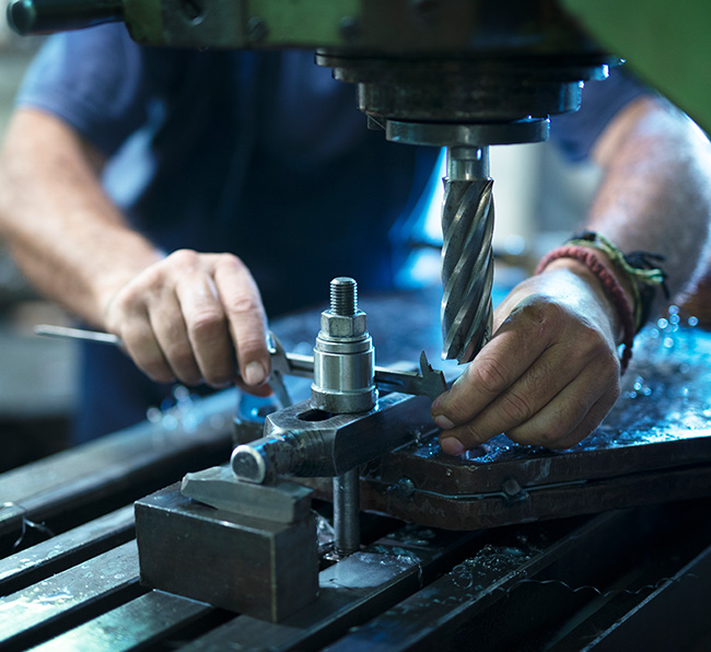
Custom welding is particularly suitable when a component is too complex or application-specific for a standardized welded product.
It can be valuable for machine frames, structural supports, equipment brackets, housings, fabricated assemblies and components combining welded structures with machined interfaces.
The process is especially relevant when several pieces need to be joined into one functional structure rather than produced from a single solid workpiece.
Design flexibility is another advantage.
Separate plates, tubes, machined blocks and other elements can be combined according to the load path and geometry required by the final assembly.
However, welding should not be selected simply because multiple metal pieces are involved.
Designers should also consider whether thermal effects are compatible with the required geometry and whether important surfaces should be machined after joining.
The best manufacturing route may combine cutting, machining, welding, dimensional correction and final inspection.
Custom welding becomes most effective when each of these stages has a clear purpose and the sequence is designed around the finished component.
Conclusion
Custom welding is not simply a more flexible version of general welding. It is an engineered manufacturing approach built around the specific geometry, materials and performance requirements of a component.
A reliable process begins with design review.
Material behavior, joint accessibility, fit-up, functional datums and critical dimensions should be understood before the welding sequence is established.
Fixturing then creates the repeatable starting condition needed for production. Heat input and welding sequence control how the assembly responds during joining, while inspection provides evidence about whether the process is producing the intended result.
For components containing precision interfaces, welding and CNC machining should be treated as connected manufacturing stages. Some geometry is best established before welding, while other critical surfaces should be finished after thermal movement has occurred.
This integrated approach is particularly valuable for complex structures and precision mechanical assemblies.
The objective is not to eliminate every dimensional change caused by welding. It is to understand where movement matters, control it where practical and plan downstream manufacturing around the final functional requirements.
When design, welding, machining and inspection are developed as one process, custom welding becomes more predictable, repeatable and suitable for demanding metal components.
FAQ
What is custom welding?
Custom welding is a joining process developed around the specific material, geometry and functional requirements of a component. It may involve TIG, MIG or other welding methods together with dedicated fixtures, controlled welding sequences, inspection and post-weld machining when the finished assembly requires additional precision.
What materials can be used for custom welding?
Custom welding can be applied to many weldable metals and alloys when the process is selected for their actual properties. Material composition, thickness, thermal behavior and surface condition influence joint preparation, heat input and filler selection, so each project should use a material-specific welding strategy.
How can distortion be controlled in custom welding?
Distortion can be managed through suitable joint design, controlled heat input, balanced welding sequences, appropriate tack welding and well-designed fixtures. The aim is not simply to minimize heat, but to control how expansion and contraction affect the critical dimensions and alignment of the finished assembly.
Can custom welded parts be CNC machined afterward?
Yes. Post-weld CNC machining is often useful when an assembly contains precision mounting faces, bores, holes or locating features. The design should include suitable machining allowance and stable reference features so the required geometry can be established after welding-related thermal movement has occurred.
What should be checked before starting a custom welding project?
Review material specifications, joint geometry, weld access, critical dimensions, fixture strategy, expected thermal movement and inspection requirements before production. If machining is required after welding, the datum plan and machining allowance should also be defined early so both processes support the same final geometry.

Latest News
Contact Us
FAQ
What types of parts can be machined?
We can machine a wide range of high-precision CNC parts for automotive, aerospace, medical devices, industrial machinery, and automation equipment, including complex geometries and custom non-standard parts.
What is the machining accuracy?
We can achieve high-precision machining with ±0.005mm tolerance and ensure consistent quality through our strict quality control system.
Can you provide small-batch and prototype manufacturing services?
Yes, we support small-batch production and prototype machining, with flexible scheduling to meet urgent client requirements.
Do you offer customized processing solutions?
Yes, we provide customized solutions with one-on-one technical support, from design review and process optimization to final machining.
How long does delivery usually take?
Delivery time depends on part complexity and quantity, typically within 1-6 weeks. We provide a detailed schedule upon order confirmation.
What certifications are available for quality management systems?
We hold ISO 9001, ISO 14001, and ISO 45001 certifications, strictly following international quality, environmental, and safety standards.
How long does delivery usually take?
Delivery time depends on part complexity and quantity, typically within 1-6 weeks. We provide a detailed schedule upon order confirmation.