
The Science Behind Precision Machined Parts: Tolerances, Datums and Process Control
Home
/
Blog
/
The Science Behind Precision Machined Parts: Tolerances, Datums and Process Control
The Science Behind Precision Machined Parts: Tolerances, Datums and Process Control
August 19, 2026
Table of Contents
Introduction
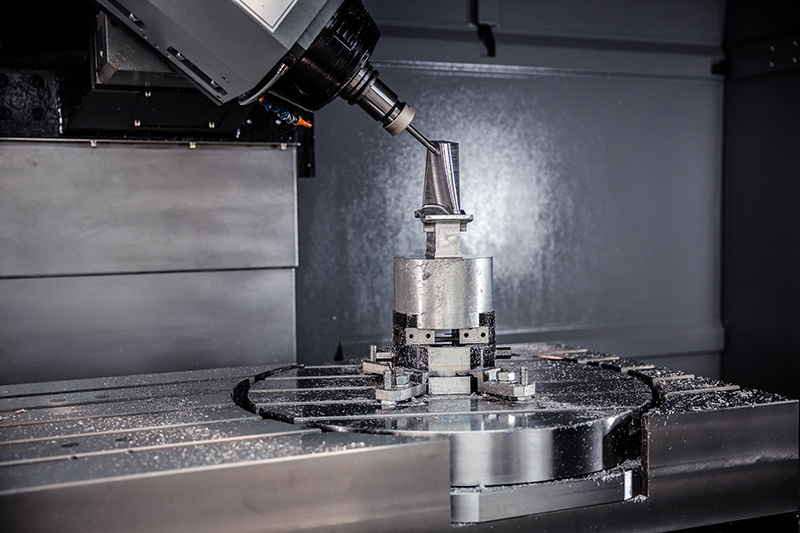
Precision machined parts are defined by more than small dimensional tolerances. A component may contain an accurately machined diameter and still fail to perform correctly if its bore position, mounting face, surface condition or relationship to another feature is unstable. For this reason, precision manufacturing should focus on how the complete geometry works as a system rather than treating every dimension as an independent target.
The difference becomes especially important when parts contain bearing interfaces, sealing surfaces, locating holes, controlled rotational features, thin walls or several machined surfaces that must align during assembly. In these situations, accuracy depends on how design intent is translated into datums, machining setups, tooling strategies and inspection methods.
Modern CNC equipment provides the programmed movement needed to manufacture complex geometry, but the final result still depends on physical conditions such as material behavior, workholding, cutting forces, tool wear and temperature. Precision machined parts are therefore created through controlled interaction between design, machining and measurement rather than by machine positioning alone.
Understanding these relationships helps engineers create drawings that communicate function more clearly and helps manufacturers develop processes that remain stable from prototypes through repeated production.
What Are Precision Machined Parts?
Precision machined parts are components produced through controlled material-removal processes where specific dimensions, geometric relationships and surface characteristics must remain within defined requirements. The broader field of machining includes processes such as turning, milling, drilling, boring and related methods used to shape workpieces by removing material.
What makes a component a precision part is not simply the use of a CNC machine. Precision becomes relevant when dimensional or geometric variation can affect assembly, motion, sealing, alignment or other aspects of performance. A simple shaft may therefore require greater manufacturing control than a visually complex housing if the shaft contains several tightly related bearing diameters.
Precision machined parts can begin from bar, plate, castings, forgings or other prepared blanks. The starting form influences the machining route because each type of workpiece provides different reference surfaces, machining allowances and material conditions. The manufacturing strategy must therefore account for both the final geometry and the condition of the material before cutting begins.
Precision Begins With Functional Design
A useful precision machining process begins by identifying which features actually control component function. A drawing may contain dozens of dimensions, but only a portion of them may directly influence fit, movement or assembly.
A bore supporting a bearing may need controlled size and position. A mounting surface may need to remain flat relative to another interface, while a pattern of holes may need accurate location because it connects the component to a larger assembly. Other external dimensions may provide only clearance and therefore require less restrictive control.
This distinction is important because applying tight requirements everywhere does not necessarily improve the finished component. Instead, it can make machining, fixturing and inspection more restrictive without creating additional functional value. Precision should be concentrated where variation produces a measurable effect on performance.
Designers can improve precision machined parts by defining meaningful references and communicating how important features relate to them. When design intent is clear, manufacturing engineers can plan machining operations around the same functional relationships rather than attempting to interpret which dimensions are actually critical after production has already begun.
Datums Connect Design, Machining and Inspection
Datums provide a common reference system for part geometry. They allow designers to define where important features should be located and give manufacturers a logical basis for setting up and inspecting the component.
A strong datum strategy should reflect the way the part functions in its final assembly. If a component sits against a primary mounting face and is positioned by a locating bore, those features may provide more meaningful references than an unrelated outside contour.
This approach creates continuity between engineering and manufacturing. The machining fixture can establish the component from surfaces that correspond to the drawing, while inspection can evaluate finished geometry from the same functional reference system.
Poor datum selection can create unnecessary uncertainty. If a part is machined from one group of reference surfaces but inspected from another, it may become difficult to determine whether an apparent dimensional problem comes from machining variation or from inconsistent interpretation of the drawing.
For precision machined parts, datums should therefore be considered early rather than added only when the drawing is nearly complete. A practical reference strategy makes both machining and quality verification easier to control.
Tolerances Should Reflect Function Instead of Maximum Precision
Tolerance defines the acceptable variation around a required dimension or geometric characteristic. Because no physical machining process produces mathematically perfect geometry, tolerances establish the range within which the part can still perform correctly.
A common mistake is assuming that a smaller tolerance automatically means a higher-quality component. In reality, the correct tolerance is the one that protects the intended function while remaining appropriate for the selected material, process and inspection method.
Bearing fits, sealing interfaces and precision locating features may require close control because small dimensional changes can alter their behavior. Clearance surfaces, external reliefs or non-functional geometry may allow significantly greater variation without affecting performance.
The same principle applies to geometric tolerances. Position, flatness, perpendicularity, runout and similar controls should describe relationships that matter to the assembly rather than being added simply to make a drawing appear more precise.
Apex’s existing guide to CNC machining tolerances discusses the relationship between functional requirements, manufacturing capability and tolerance selection in greater detail.
A useful precision drawing therefore distinguishes between critical characteristics and general geometry. This gives the manufacturing team a clearer understanding of where process stability and inspection effort should be concentrated.
Material Behavior Changes Precision Machining Strategy
Material selection influences both the final performance of precision machined parts and the way those parts behave during manufacturing. Aluminum alloys, steels, stainless steels, cast materials and engineering plastics respond differently to cutting forces, temperature and workholding.
A relatively rigid material may remain stable while thin features are machined, whereas a more flexible workpiece can move under the same cutting load. Harder materials can increase tool loading and wear, while some materials may generate heat or chips that require a different machining strategy.
Material condition can be just as important as material type. A machined billet, casting and forging may all be made from related alloys while requiring different initial setup strategies because their starting geometry and internal conditions are not identical.
Substantial material removal can also change how a workpiece behaves. If a component contains residual stress, removing large volumes of material can alter the balance within the part and cause movement before finishing is complete. Roughing and finishing may therefore need to be separated when dimensional stability is important.
For precision machined parts, material should not be treated simply as a drawing specification. It is one of the variables that determines tooling, workholding, machining sequence and final inspection strategy.
Workholding Determines Whether Precision Can Be Repeated
A CNC machine can follow its programmed path accurately while the finished component still varies if the workpiece is not located consistently. Workholding therefore forms one of the foundations of precision machining.
The fixture must hold the part securely enough to resist cutting forces while preserving access to the required geometry. At the same time, clamping should not introduce unnecessary deformation into thin or flexible components.
This balance can become difficult with complex precision machined parts. A thin housing may require support around a large cavity, while an irregular casting may not provide stable initial surfaces for locating. A long shaft can require additional support because cutting forces may cause it to deflect during turning.
Manufacturing sequence also affects fixture planning because reference surfaces can disappear as machining progresses. A convenient raw-material face used during the first operation may be completely removed later, so the process must establish new controlled surfaces before that reference is lost.
Good workholding is therefore not simply about holding the component tightly. It is about establishing a repeatable relationship between the part, the machine and the functional geometry defined on the drawing.
Cutting Tool Deflection Can Change Finished Geometry
Every cutting tool experiences load as it removes material. When that load acts on a long or slender tool, small amounts of deflection can occur even when the programmed tool path itself is correct.
This becomes important in deep cavities, small internal radii and other features that require extended tooling. A cutter reaching deeply into a pocket generally has less rigidity than the same tool used with a shorter extension, making vibration and dimensional variation more difficult to control.
Part design directly influences this condition. Extremely small internal corner radii may require smaller tools, while deep narrow pockets can force the use of longer cutters. If these features do not provide functional value, they can create manufacturing difficulty without improving part performance.
Turning creates a similar problem with slender workpieces. Instead of the tool bending significantly, the rotating part itself may deflect under cutting force. The resulting diameter can therefore vary even though machine positioning remains correct.
Precision machined parts benefit when geometry allows practical tooling and stable cutting conditions. Design for manufacturability does not require eliminating complex features, but it should ensure that the complexity serves a genuine engineering purpose.
Tool Wear Must Be Managed Across Production
A new cutting edge does not behave exactly like the same cutting tool after repeated machining. As tools wear, cutting forces, heat generation and surface condition can gradually change, creating dimensional drift over a production run.
This distinction is particularly important when moving from prototype machining to repeated production. A prototype may be produced successfully with fresh tooling and close operator attention, while later components need to remain within the same requirements as tool condition gradually changes.
Precision machining therefore requires a strategy for monitoring or compensating for wear. Critical dimensions may be inspected at defined stages, tool offsets may be adjusted when appropriate, and cutting tools may be replaced according to proven process behavior rather than only after obvious failure.
The objective is not to eliminate tool wear, which is a natural part of material removal, but to prevent predictable wear from becoming uncontrolled part variation. Inspection data can provide useful feedback by showing whether a dimension is gradually moving toward one side of its allowed range.
When machining precision parts repeatedly, tooling should therefore be treated as a process variable that changes over time rather than as a fixed condition.
Thermal Stability Matters When Dimensions Become Critical
Heat is generated throughout machining as the cutting tool interacts with the workpiece. The tool, part and machine structure can all experience temperature changes, and materials expand or contract as those conditions change.
For many general components, the effect may have little practical significance. When precision machined parts contain demanding dimensions or long machining cycles, however, thermal variation can become one source of process inconsistency.
Heavy roughing can introduce different thermal conditions from light finishing. Measuring a component immediately after substantial material removal may also represent a different condition from measuring the same part after it has stabilized.
Process planning can reduce these effects by separating major material removal from final finishing when necessary and by maintaining more consistent manufacturing conditions around critical operations.
The objective is not to create unnecessary environmental controls for every component. Instead, thermal behavior should be considered when unexplained dimensional variation appears or when the drawing contains features sensitive enough for temperature-related movement to matter.
Precision is easier to reproduce when machining and inspection are performed under reasonably consistent conditions.
Surface Finish and Dimensional Precision Are Different Requirements
A component can satisfy dimensional tolerance while still having a surface texture that is unsuitable for its function. For precision machined parts, surface finish should therefore be evaluated separately from size and geometry.
Bearing seats, sealing surfaces and sliding interfaces may depend on both dimensional control and surface condition. A clearance pocket or hidden external surface may not require the same level of finish even when it is machined accurately.
Tool geometry, feed, cutting conditions, material behavior and vibration all affect the surface left behind during machining. A dimension may therefore remain correct while surface quality changes because of tool wear or unstable cutting conditions.
Secondary finishing processes can be used when the primary machining operation is not the most practical way to establish a particular surface. Grinding, for example, may complement turning or milling when selected features require additional dimensional or surface control.
The strongest drawing specifies surface requirements where they support function rather than demanding highly controlled finishes across every visible or machined area.
Setup Planning Protects Relationships Between Features
Complex precision machined parts often require more than one machining orientation. Whenever the workpiece is removed, repositioned or referenced again, the manufacturing process must re-establish its relationship with the machine.
This creates another possible source of variation.
Suppose a bore is created during one setup and a mounting surface is machined after the component has been repositioned. The relationship between the two features depends on both machine accuracy and the reliability of the second setup.
For this reason, features with strong functional relationships can benefit from being machined within the same stable reference condition whenever geometry and equipment allow it.
Multi-axis machining can reduce some repositioning by giving the cutting tool access to several sides of a component while the workpiece remains in a controlled setup. However, fewer setups are not automatically better if the resulting tool access or fixture stability becomes poor.
Apex’s CNC machining services include milling, turning and multi-axis processing for complex high-precision components. The process selected for a precision part should still be based on its geometry, functional relationships and inspection requirements rather than the number of available machine axes.
The goal is meaningful setup planning: keep critical relationships stable while using additional operations only where they genuinely improve manufacturability.
How Precision Machined Parts Are Controlled Through the Process
Precision machining is strongest when quality is built into each manufacturing stage instead of being evaluated only after the component is complete. Material preparation, reference creation, rough machining, finishing and inspection should follow a planned sequence in which every operation supports the next.
Early machining operations often establish datums and stable reference surfaces. Roughing then removes larger amounts of material while leaving sufficient stock for finishing. Critical dimensions can be completed after the workpiece has reached a more stable geometry, and inspection can verify whether the process remains within the intended range.
This approach also helps identify where variation enters production. If a dimension is already incorrect after an intermediate operation, the problem can be investigated before additional machining makes the root cause harder to identify.
The following table summarizes several variables that influence precision machined parts and shows why controlling only the CNC program is not enough.
| Process Factor | Possible Effect on Precision | Practical Control Approach |
|---|---|---|
| Functional datums | Misaligned feature relationships | Use references connected to assembly function |
| Material condition | Movement or inconsistent cutting behavior | Match machining strategy to actual workpiece material |
| Workholding | Positioning error or deformation | Use repeatable locating and controlled clamping |
| Tool rigidity | Deflection in deep or narrow features | Provide practical access and suitable tool geometry |
| Tool wear | Gradual dimensional drift | Monitor critical dimensions and tool condition |
| Setup changes | Relationship error between operations | Group related features where practical |
| Temperature | Dimensional variation | Maintain consistent conditions for critical operations |
| Surface requirements | Functional interface problems | Specify finish according to application |
| Inspection method | Unrecognized process variation | Match measurement capability to drawing requirements |
| Process documentation | Inconsistent repeat production | Record proven setups, tools and inspection points |
The table illustrates an important principle: precision is accumulated throughout the process. A final inspection system can detect variation, but it cannot replace a manufacturing route that controls the sources of that variation.
Inspection Should Confirm Function, Not Only Dimensions
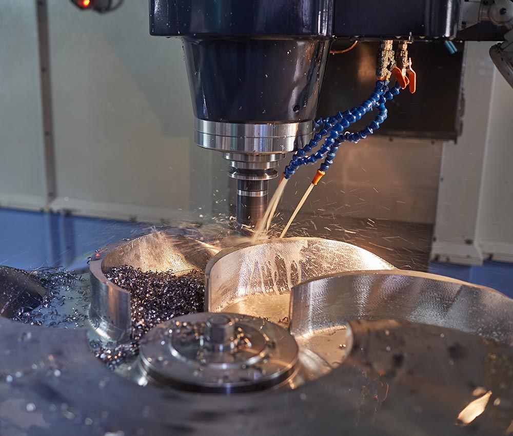
Inspection is an essential part of producing precision machined parts because manufacturing requirements need a reliable method of verification.
Different features require different measurement strategies. External diameters, internal bores, surface relationships and positional characteristics cannot always be evaluated effectively using the same type of measuring instrument.
Measurement should also follow the datum structure of the engineering drawing. If inspection references the component differently from the machining and design systems, interpreting the result can become more difficult.
In-process inspection can provide additional value by detecting changes before manufacturing is complete. A critical diameter moving gradually toward its tolerance limit can indicate tool wear, while changes in feature position can reveal fixture or setup problems.
This turns inspection into more than a final acceptance process. Measurement data becomes feedback that helps manufacturers understand whether the machining system remains stable.
For precision machined parts, the quality department and production process should therefore operate as connected systems rather than as separate stages.
Prototype Precision Parts Should Develop the Manufacturing Process
Producing one accurate prototype does not automatically mean the manufacturing route is ready for repeated production. Prototype machining often involves additional attention, frequent measurements and adjustments based on what the machining team learns from the first workpiece.
Those observations provide valuable process information.
A thin wall may move more than expected. A deep cavity may require a different tool. A datum may be difficult to locate consistently, or a critical surface may be easier to finish during a different stage of machining.
These findings should be incorporated into the process before additional parts are produced. Fixture design can be refined, tool paths can be updated and inspection points can be adjusted according to actual manufacturing behavior.
A successful prototype demonstrates that the component can be produced. A successful production process demonstrates that the same functional geometry can be reproduced consistently without depending on repeated improvisation.
Precision machined parts therefore benefit when prototype manufacturing is treated as process development rather than only as part delivery.
Repeatability Is the Real Test of Precision Machining
Precision and repeatability are closely related but should not be treated as identical concepts. A manufacturer may produce one component very close to its nominal dimensions while still having difficulty maintaining the same result across additional parts.
Repeated manufacturing introduces changing conditions. Tools wear, new workpieces are loaded, fixtures are repeatedly opened and closed, raw material batches may change and machines operate through extended production cycles.
A stable process needs to account for these conditions.
Critical features should have clearly defined inspection methods, while tooling and fixture strategies should remain consistent enough to support the same reference relationships. Process adjustments should be based on measured trends rather than informal correction.
Documentation becomes increasingly important at this stage. If a specific machining sequence or setup adjustment is necessary for one difficult feature, that information should become part of the established manufacturing route rather than remaining only with one operator.
The real measure of precision machining is therefore not how close the best part is to its nominal dimension, but whether functionally acceptable geometry can be reproduced consistently throughout production.
Common Design Problems That Reduce Precision
Some precision problems begin before manufacturing starts because the component geometry makes stable machining unnecessarily difficult.
Very thin unsupported walls can move under cutting forces. Deep narrow pockets may require long tools with reduced rigidity, while extremely small internal corner radii can restrict cutter selection. Features positioned across many different orientations can increase setup count even when their functional requirements are relatively simple.
Over-tolerancing creates another common problem. If almost every dimension is assigned a restrictive requirement, manufacturing and inspection become more complicated without necessarily improving assembly performance.
Poor datum selection can also reduce clarity. When functional features are controlled from unrelated external surfaces, both machining and inspection may have difficulty reproducing the intended assembly relationship.
Design for manufacturability helps identify these conditions before production. The goal is not to remove complex geometry that the product genuinely requires, but to eliminate manufacturing difficulty that provides no meaningful functional advantage.
Precision machined parts are often easier to control when design decisions acknowledge the physical behavior of tools, fixtures and materials.
When Do Parts Actually Need Precision Machining?
Not every machined component requires the same level of dimensional control. Precision machining is most valuable when variation can directly influence component function.
Bearing fits, sealing interfaces, rotational alignment, controlled motion and accurate positioning are typical situations where machining precision can affect performance. Parts that must assemble repeatedly with other components may also require more careful control of geometric relationships.
Complexity alone does not define the requirement. A highly complex decorative component may tolerate relatively generous variation, while a simple cylindrical shaft can require much tighter control because its diameter and runout determine how a bearing operates.
Engineers should therefore determine precision requirements by considering what would happen if each feature moved within its possible manufacturing range.
If a dimensional change creates interference, leakage, misalignment, vibration or another functional problem, that feature deserves closer attention. If variation has no meaningful effect, applying an unnecessarily restrictive requirement can make the manufacturing process more difficult without improving the product.
How to Evaluate a Precision Machined Parts Manufacturer
Evaluating a machining manufacturer should begin with process capability rather than machine specifications alone. Advanced CNC equipment is important, but reliable precision also depends on drawing interpretation, fixture design, tooling knowledge, material experience and inspection.
A capable manufacturing team should be able to identify which dimensions and datums control the part’s function and develop the machining route around those requirements. If the design contains difficult tool access, unstable walls or unnecessarily restrictive tolerances, those risks should be identified before production begins.
Machining capability should also correspond to component geometry. Rotational parts may require turning and boring, while complex housings may depend more heavily on milling or multi-axis operations. Some parts can also require grinding or other finishing processes after primary CNC machining.
Inspection capability should match the characteristics shown on the drawing rather than being treated as a generic final check. The manufacturer should understand how measurement results relate to machining processes and how those results can be used to maintain consistency.
The strongest machining partner therefore combines equipment with engineering judgment and process control. Precision is most reliable when every stage of manufacturing follows the same functional interpretation of the component.
Conclusion
Precision machined parts are not created simply by asking a CNC machine to hold tighter dimensions. Reliable precision comes from controlling the complete relationship between design intent, material behavior, datums, workholding, tooling, machining sequence and inspection.
Functional design provides the starting point by identifying which features genuinely affect assembly and performance. Datums then connect those requirements to manufacturing and measurement, while tolerance strategy determines how much variation can be accepted without compromising function.
During machining, workholding and tool rigidity influence whether programmed movement becomes accurate physical geometry. Tool wear and thermal conditions can introduce variation over time, making process monitoring particularly important during repeated production.
Inspection completes the system by providing evidence about whether the manufacturing route remains stable. When that information is used to improve machining rather than only accept or reject finished parts, precision becomes more predictable.
The central principle is simple: precision should be engineered into the process rather than inspected into the final component. When design, manufacturing and measurement work from the same functional requirements, precision machined parts become easier to reproduce, easier to verify and more reliable in repeated production.
FAQ
What are precision machined parts?
Precision machined parts are components produced through controlled machining processes where specific dimensions, geometric relationships and surface characteristics must remain within defined limits. Their quality depends on design, material, tooling, workholding, process stability and reliable inspection rather than CNC programming alone.
What materials are used for precision machined parts?
Precision machined parts can be produced from aluminum alloys, steels, stainless steels, cast materials, engineering plastics and other machinable materials. Material selection should consider both final performance and machining behavior because rigidity, tool wear, thermal response and dimensional stability can affect the process.
What determines the accuracy of precision machined parts?
Accuracy depends on machine condition, functional datums, fixture stability, cutting-tool rigidity, tool wear, material behavior, temperature, machining sequence and inspection. The most reliable processes control these factors together so critical feature relationships remain consistent throughout production.
Why are datums important for precision machined parts?
Datums create the reference system used to locate and measure important features. When datums reflect how the component functions in its final assembly, machining and inspection can work from the same geometric relationships, making positional accuracy and repeated manufacturing easier to control.
How can precision machined parts be made more repeatable?
Repeatability improves when successful prototype conditions are converted into controlled production methods. Stable fixtures, documented tool strategies, defined machining sequences and in-process inspection help identify tool wear or process drift before variation affects completed components.
Latest News
Contact Us
FAQ
What types of parts can be machined?
We can machine a wide range of high-precision CNC parts for automotive, aerospace, medical devices, industrial machinery, and automation equipment, including complex geometries and custom non-standard parts.
What is the machining accuracy?
We can achieve high-precision machining with ±0.005mm tolerance and ensure consistent quality through our strict quality control system.
Can you provide small-batch and prototype manufacturing services?
Yes, we support small-batch production and prototype machining, with flexible scheduling to meet urgent client requirements.
Do you offer customized processing solutions?
Yes, we provide customized solutions with one-on-one technical support, from design review and process optimization to final machining.
How long does delivery usually take?
Delivery time depends on part complexity and quantity, typically within 1-6 weeks. We provide a detailed schedule upon order confirmation.
What certifications are available for quality management systems?
We hold ISO 9001, ISO 14001, and ISO 45001 certifications, strictly following international quality, environmental, and safety standards.
How long does delivery usually take?
Delivery time depends on part complexity and quantity, typically within 1-6 weeks. We provide a detailed schedule upon order confirmation.